Discharge system and process of refuse incinerator flue gas

A waste incinerator and flue gas technology, which is applied in the exhaust system and process field of waste incinerator flue gas, can solve the problems of limited deacidification efficiency, difficulty in completely realizing ultra-low emission treatment, and difficulty in emission control

Inactive Publication Date: 2019-04-05
ZHEJIANG DOWAY ADVANCED TECH CO LTD
View PDF10 Cites 12 Cited by
  • Summary
  • Abstract
  • Description
  • Claims
  • Application Information

AI Technical Summary

Problems solved by technology

Semi-dry deacidification, dry deacidification and wet deacidification processes all have limitations in deacidification efficiency, which can achieve lower emission indicators, but it is difficult to fully achieve the purpose of ultra-low emission treatment
[0012] To sum up, the current domestic traditional waste inci

Method used


Image

  • Discharge system and process of refuse incinerator flue gas

Examples


Embodiment Construction

[0042] In order to further explain the technical solution of the present invention, the present invention will be described in detail below through specific examples.

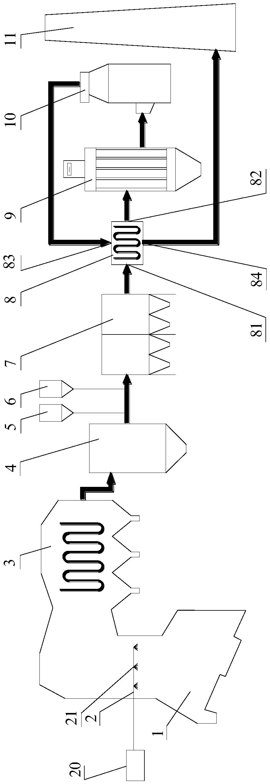
[0043] Please refer to figure 1 As shown, the present invention provides a waste incinerator flue gas discharge system, comprising: an incinerator 1 connected in sequence, a waste heat boiler device 3, a semi-dry rotary spray device 4, a bag dust removal device 7, and a gas-gas heat exchanger (GGH) 8, low temperature plasma reactor 9 and wet deacidification tower 10.

[0044] The incinerator 1 is provided with an SNCR denitrification device 2 for primary denitrification of the flue gas generated by the incinerator 1 . The semi-dry rotary spraying device 4 and the bag dust removal device 7 are connected through a flue, and the flue is provided with an activated carbon flue mixing injection device 5 and a dry powder flue mixing injection device 6 .

[0045] The gas-gas heat exchanger 8 has a hot gas inlet 81, a h...


PUM


Abstract

The application discloses a discharge system and process of refuse incinerator flue gas. The process includes the steps of denitrifying; removing acid gas and divalent mercury compounds by a semi-dryprocess; carrying out activated carbon adsorbing and dry powder deacidifying; removing dust; carrying out flue gas heat exchanging; decomposing pollutants by low temperature plasma; carrying out wet deacidifying. The system and process herein are suitable for synchronous and efficient deep removal of various pollutants (including particles, nitric oxides, sulfur oxides, dioxin, hydrogen chloride,hydrogen fluoride, mercury and other heavy metals), and can provide ultralow-concentration discharge of refuse incineration flue gas, with NOX<50 mg/Nm<3>, SO2<35 mg/Nm<3>, dioxin TEQ<0.01 ng/Nm<3>, and discharge indexes of HF, HCl, mercury and other heavy metals greatly decreased.

Description

technical field [0001] The invention relates to the field of air pollution purification, in particular to a waste incinerator flue gas discharge system and process. Background technique [0002] With the rapid development of my country's economy, the rapid improvement of people's living standards, the continuous improvement of the urbanization process, the generation of various types of garbage is also increasing sharply. According to the "Annual Report on the Prevention and Control of Environmental Pollution by Solid Waste in Large and Medium-sized Cities in China in 2017" published by the Ministry of Environmental Protection, in 2016, 214 large and medium-sized cities produced 188.505 million tons of domestic waste, with an annual growth rate of 8-10%. Increase. Domestic waste disposal methods are mainly landfill and waste incineration. Waste landfill consumes a lot of land resources, and is prone to sewage leakage to pollute soil and groundwater, destroy land resources,...

Claims


Application Information

Patent Timeline
IPC IPC(8): B01D53/75B01D53/78B01D53/56B01D53/80B01D53/40B01D53/68B01D53/83B01D50/00F28D7/08F23J15/06F23J15/02F22B1/18
CPCB01D53/06B01D53/32B01D53/40B01D53/56B01D53/68B01D53/75B01D53/78B01D53/80B01D53/83F22B1/1807F23J15/02F23J15/06F28D7/08B01D2253/102B01D2258/0291B01D50/60Y02E20/30
Inventor 施小东翁林钢叶青戚科技施秦峰
Owner ZHEJIANG DOWAY ADVANCED TECH CO LTD
Why Eureka
Try Eureka