
A polygeneration device and method for coal gas low-nitrogen oxide combustion power generation

A low-nitrogen oxide combustion power generation technology, which is applied to combustion methods, steam generating devices, and combustion using multiple fuels, can solve problems such as increased difficulty in desulfurization, blockage of catalyst micropores, and poisoning and deactivation of SCR catalysts. Improve the effect of comprehensive added value and clean cascade utilization

Active Publication Date: 2017-04-19
SHAANXI YANCHANG PETROLEUM GRP
View PDF10 Cites 0 Cited by
  • Summary
  • Abstract
  • Description
  • Claims
  • Application Information

AI Technical Summary

Problems solved by technology

However, due to the high dust concentration, the wear and corrosion of the catalyst is serious, and it can also cause the micropore blockage of the catalyst, which affects its life and activity; the SO in the flue gas 2 Under the catalytic action of the denitrification catalyst, it will be converted into SO 3 , the difficulty of subsequent desulfurization increases
For ②, although the dust concentration is reduced, it is necessary to add a flue gas reheating system, which increases investment and operating costs, and there is also SO in the flue gas 2 will be converted to SO 3 The problem
For ③, although there is no impact of dust erosion in the flue gas on the catalyst life and activity, there is no SO in the flue gas 2 will be converted to SO 3 However, it also faces the problem of adding a flue gas reheating system, which increases investment and operating costs
At the same time, the biggest problem with the SCR method is the use of ammonia, and heavy metals such as lead, chromium, cadmium, and arsenic that are ubiquitous in coal-fired flue gas may poison and deactivate the SCR catalyst, seriously affecting its normal life.

Method used


Image

  • A polygeneration device and method for coal gas low-nitrogen oxide combustion power generation

Examples


Embodiment Construction

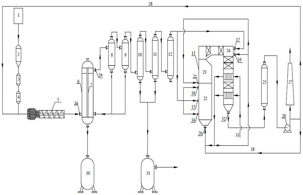
[0026] In order to make the technical solutions and advantages of the present invention clearer, the present invention will be further described in detail below in conjunction with the accompanying drawings and embodiments.

[0027] see figure 1 , the device of the present invention includes a pulverized coal feeding device and a pulverized coal upgrading conversion reactor 6 connected with the pulverized coal feeding device, the lower end of the pulverized coal upgrading conversion reactor 6 is connected with an ash storage tank 30, and the pulverized coal upgrading The crude gas containing tar and ash output from the conversion reactor 6 is connected to the dust removal and separation device through the pulverized coal upgrading conversion reactor 6 outlet 29, and the tar in the crude gas recovered by the dust removal and separation device is sent into the tar storage tank 31, The gas outlet of the dust removal and separation device is desulfurized by the desulfurization tow...


PUM

PropertyMeasurementUnit
particle size (mesh)aaaaaaaaaa

Abstract

The invention provides a poly-generation apparatus and method using low nitrogen oxides in coal gas for combustion power generation. According to the invention, one or more low rank coal selected from the group consisting of brown coal, long flame coal, sub-bituminous coal and soft coal are added into a fine coal upgrading conversion reactor for rapid conversion, crude coal gas produced after conversion undergoes dedusting and purifying, oil-gas separation, and desulphurization and purification; and purified coal gas is successively injected into a boiler for combustion through graded combustion nozzles. Compared with the prior art, the invention has the following advantages: a desired air excess coefficient is small, combustion temperature is lower than a typical temperature--1400 DEG C at which a great amount of thermal NOx is produced, so production of thermal NOx in the process of combustion is radically inhibited and production of fuel NOx and rapid NOx is avoided; the concentration of respirable particulates like SO2, PM2.5 and PM10 in combustion flue gas is extremely low, and ultra-low concentration discharge of SO2 and NOx can be realized; and the combustion flue gas is almost free of heavy metals like lead, chromium, cadmium, arsenic and mercury.

Description

technical field [0001] The invention relates to the technical field of high-efficiency clean conversion and utilization of coal and clean combustion of coal gas for power generation, in particular to a polygeneration device and method for coal gas low-nitrogen oxide combustion power generation. Background technique [0002] During the coal combustion process of power plant boilers, there are three main sources of NOx, namely, thermal NOx, fuel NOx, and rapid NOx. At normal combustion temperatures, NOx accounts for more than 90% of the NOx produced by coal combustion, and NO 2 Accounted for 5% to 10%. At present, the NOx control methods in coal-fired power plant boilers are mainly divided into three categories: one is to use low-nitrogen fuels or denitrify fuels before combustion; the other is to use low-NOx combustion methods; the third is to denitrify coal-fired flue gas. Coal contains the most nitrogen, followed by fuel oil, and generally there is no or very little nitro...

Claims


Application Information

Patent Timeline
Patent Type & Authority Patents(China)
IPC IPC(8): F23C5/08F23C7/02F23C9/00F22B33/18F23J15/02C10J3/48C10J3/56C10J3/64C10J3/84F01K11/02F01D15/10
Inventor 李大鹏王明峰王宁波任健张健吴升潇米建新靳皎郝婷孔少亮王武生
Owner SHAANXI YANCHANG PETROLEUM GRP
Learn More