Vacuum welding equipment capable of automatically detecting weld joint and using method of vacuum welding equipment

A vacuum welding and automatic detection technology, which is applied in welding equipment, welding equipment, auxiliary welding equipment, etc., can solve the problems that affect the welding quality of welded parts, the health of personnel, affect production efficiency, and a large amount of smoke

Inactive Publication Date: 2019-04-05
GUANGXI NANNING SHENGQIAN TECH DEV CO LTD
View PDF0 Cites 8 Cited by
  • Summary
  • Abstract
  • Description
  • Claims
  • Application Information

AI Technical Summary

Problems solved by technology

[0002] In the existing welding equipment, there are many technologies such as explosive welding and vacuum welding. Among them, vacuum electron beam welding is the welding of materials in a vacuum environment. Electron beams can weld different metals and alloy materials, especially high refractory metals. Welding, and the welding precision is high, the efficiency of welding large and thick parts is higher, the welded joints are of high purity, the weld seam is pure, smooth, mirror-like, and free of oxidation and other defects; but at present, due to the long vacuuming time of large-scale vacuum electron beam welding, about It takes 10-15 minutes, and repeated vacuuming is required for each welding, which affects the production efficiency of the equipment. Especially when welding small parts, continuous welding cannot be carried out, and the vacuuming time seriously affects production efficiency; in addition, in the existing welding process, there are It is necessary to switch to use argon arc welding equipment for alternate welding operations. During the welding process, a large amount of smoke is generated, which seriously affects the welding quality of the welded parts and the health of personnel. At the same time, the weld quality cannot be automatically detected after welding, which affects production efficiency.

Method used


Image

  • Vacuum welding equipment capable of automatically detecting weld joint and using method of vacuum welding equipment
  • Vacuum welding equipment capable of automatically detecting weld joint and using method of vacuum welding equipment
  • Vacuum welding equipment capable of automatically detecting weld joint and using method of vacuum welding equipment

Examples


Embodiment 1

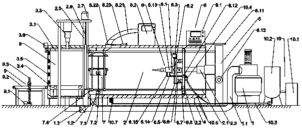
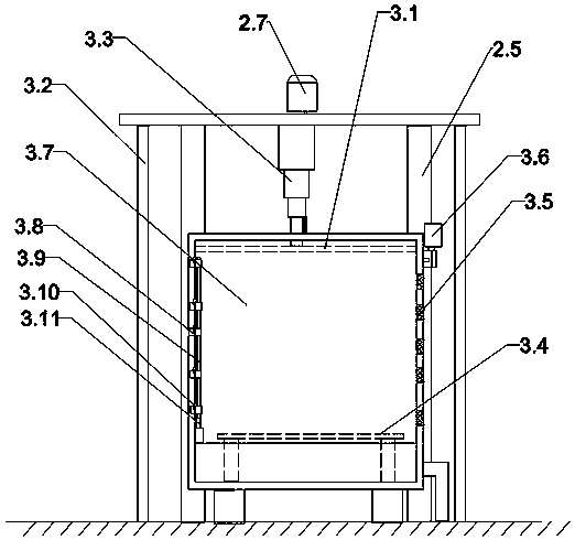
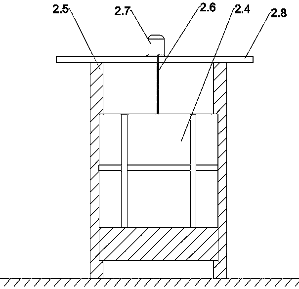
[0037]A vacuum welding device capable of automatically detecting weld seams, comprising a vacuum device 1, a welding vacuum chamber 2, a feeding vacuum chamber 3, an electron beam welding device 6, a welding workbench 7, an argon arc welding device 8, a nitrogen generating device 10 and Equipment support foot 4, the vacuum device 1 is arranged on the right side of the vacuum welding equipment, the vacuum device 1 is provided with a vacuum pipeline 1.1, and the vacuum pipeline 1.1 is respectively connected to the welding vacuum chamber 2 and the feeding vacuum chamber 3, the A solenoid valve I1.2 is provided before the vacuum pipeline 1.1 is connected to the welding vacuum chamber 2, and a solenoid valve II1.3 is provided before the vacuum pipeline 1.1 is connected to the feed vacuum chamber 3; the nitrogen making device 10 is located in the vacuum device 1 On the right side, the nitrogen generator 10 includes a nitrogen generator 10.1 and a nitrogen storage tank 10.2, the nitro...

Embodiment 2

[0044] Embodiment 2 is basically the same in structure and principle as Embodiment 1, except that the vacuum insulated infusion tube 10.3 is connected to the vacuum insulated infusion hose 10.5, and the vacuum insulated infusion hose 10.5 is provided with a vaporizer 10.7, the vaporizer 10.7 is connected to the liquid nitrogen central distributor 7.17. When the weldment is heated as a whole, the cooling cover lifting hydraulic cylinder 7.16 tops the cooling cover 7.15 to the top of the welding workpiece, and the vaporizer 10.7 starts up to 99.99% purity After gasification, the liquid nitrogen enters the liquid nitrogen central distributor 7.17 and sprays it on the welding work through the electromagnetic nozzle 7.19 to carry out nitrogen protection heating, so that the overall heating of the welding workpiece is more uniform.

Embodiment 3

[0046] The structure and principle of this embodiment 3 are basically the same as that of embodiment 1. The difference is that the workbench 7.11 is also provided with an overturning platform 7.8, and the bottom of the overturning platform 7.8 is provided with a semicircular gear 7.10. The bench 7.11 is hinged by the hinge II 7.9, the side of the working bench 7.11 is fixed with an overturning motor 7.13, the output of the overturning motor 7.13 is provided with an overturning gear 7.12, the overturning gear 7.12 meshes with the semicircular gear 7.10, and the overturning table 7.8 When welding the workpiece, it can drive the weldment to turn over by 180° front and back to adapt to different welds.


PUM


Abstract

The invention provides vacuum welding equipment capable of automatically detecting a weld joint and a using method of the vacuum welding equipment. The vacuum welding equipment comprises a vacuum device, a welding vacuum chamber, a feeding vacuum chamber, an electron beam welding device, a welding worktable, an argon arc welding device, a nitrogen generation device and a weld joint detecting device; the welding vacuum chamber and the feeding vacuum chamber are provided with a piston sealing plate and a lifting sealing plate correspondingly; the electron beam welding device is arranged on the piston sealing plate, and the welding worktable can be overturned by 180 degrees and rotated by 360 degrees; the argon arc welding device is mounted on the piston sealing plate in a replaceable mode, and the nitrogen generation device can provide liquid nitrogen for a welding gun and a weldment for cooling; and the weld joint detecting device is arranged at the bottom of a feeding conveying belt. Adetecting frame is arranged to be of a semi-arc structure and can rotate, detection through a probe on the detecting frame is more thorough, when the weldment is transferred out from the equipment, the quality of the weld joint of the weldment can be quickly, conveniently and accurately detected, and the production efficiency is effectively improved.

Description

technical field [0001] The invention belongs to the technical field of vacuum welding, and relates to a vacuum welding equipment capable of automatically detecting welding seams and a use method thereof. Background technique [0002] In the existing welding equipment, there are many technologies such as explosive welding and vacuum welding. Among them, vacuum electron beam welding is the welding of materials in a vacuum environment. Electron beams can weld different metals and alloy materials, especially high refractory metals. Welding, and the welding precision is high, the efficiency of welding large and thick parts is higher, the welded joints are of high purity, the weld seam is pure, smooth, mirror-like, and free of oxidation and other defects; but at present, due to the long vacuuming time of large-scale vacuum electron beam welding, about It takes 10-15 minutes, and repeated vacuuming is required for each welding, which affects the production efficiency of the equipme...

Claims


Application Information

Patent Timeline
Patent Type & Authority Applications(China)
IPC IPC(8): B23K15/06B23K9/16B23K9/32B23K37/047
CPCB23K9/16B23K9/32B23K15/06B23K37/047
Inventor 钟安祺
Owner GUANGXI NANNING SHENGQIAN TECH DEV CO LTD
Why Eureka
Try Eureka