Satellite-borne laser radar foot point accurate positioning method based on surface model

A surface model and lidar technology, applied in the field of remote sensing, can solve the problems of deviation of elevation measurement results, difficulties in high-precision terrain data, and the use of flat surface areas as elevation control points, etc., to achieve high universality and high plane positioning accuracy Effect

Active Publication Date: 2019-04-16
INST OF REMOTE SENSING & DIGITAL EARTH CHINESE ACADEMY OF SCI
View PDF7 Cites 6 Cited by
  • Summary
  • Abstract
  • Description
  • Claims
  • Application Information

AI Technical Summary

Problems solved by technology

However, although the absolute elevation accuracy of the decimeter level of the laser altimeter can meet the needs of the ground elevation control point, its plane offset of more than ten meters or even tens of meters makes its laser footpoint only available as an elevation control point in the flat surface area. use
By matching the waveform with the known surface DSM (Digital Surface Model) and capturing the surface spot by the detector array, the plane coordinates of the satellite’s laser foot point have a positioning error of about 10m to 30m, which is only 70m in size. As far as the GLAS system is concerned, in complex surface areas, the deviation of the center of the light spot will cause serious deviations in the elevation measurement results
[0003] my country has a vast territory, rich resources, complex and diverse topography and features, plains, mountains, forests, cities, suburbs, ice sheets, basins and other topography and features are complete, but in some high mountain areas with complex terrain, forest areas with diverse vegetation, It is difficult to obtain high-precision terrain data

Method used


Image

  • Satellite-borne laser radar foot point accurate positioning method based on surface model
  • Satellite-borne laser radar foot point accurate positioning method based on surface model
  • Satellite-borne laser radar foot point accurate positioning method based on surface model

Examples


Embodiment

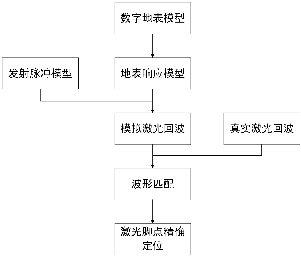
[0032] figure 1 For the overall flow diagram of the present invention, refer to figure 1 As shown, the present embodiment discloses a method for precise positioning of spaceborne laser radar feet based on terrain features, including the following steps:

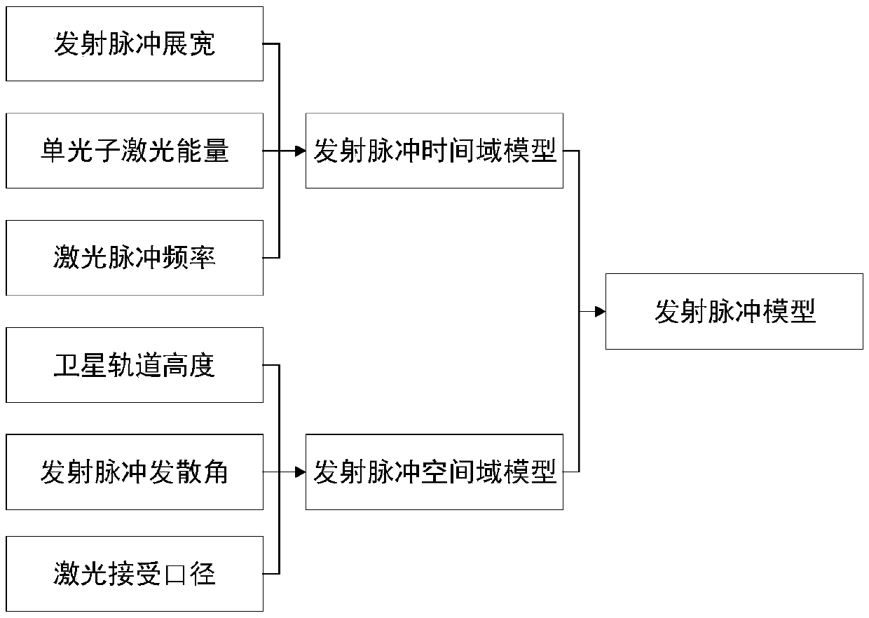
[0033] S1. Based on the satellite orbit parameters and launch pulse parameters, establish a simulated laser radar launch pulse model:

[0034] figure 2 For the schematic flow chart of generating the emission pulse model of the present invention, refer to figure 2 As shown, the implementation process of step S1 is:

[0035] S11. Establish a laser pulse time-domain model by setting parameters such as laser emission pulse width, laser energy, laser pulse frequency, and emission pulse duration, and its time-domain energy distribution is a one-dimensional Gaussian distribution;

[0036] Among them, the time domain model of the transmitted pulse is expressed as:

[0037]

[0038] In formula (1), E(t) is the laser emission...


PUM


Abstract

The invention discloses a satellite-borne laser radar foot point accurate positioning method based on a surface model, and the method comprises the steps: firstly, building a simulation laser radar emission pulse model based on satellite orbit parameters and emission pulse parameters; establishing a surface target response function based on the digital surface model data; and finally, simulating and generating a simulated laser echo waveform by using the generated emission pulse model and a target surface response function, comparing and analyzing the simulated laser echo waveform with an actual waveform, and accurately determining the position of the laser radar foot point by moving the laser spot step by step. The satellite-borne laser radar foot point accurate positioning is carried outbased on waveform simulation and waveform matching, and the surface model can accurately describe various complex surfaces, so that the laser foot point plane positioning precision is high, and the requirements of obtaining high-precision topographic data and national geographic mapping in the later period can be met. The method is high in universality, and can be applied to various satellite settings and laser foot points in various ground environments such as forests, cities, flat grounds and mountainous regions in a positioning manner.

Description

technical field [0001] The invention relates to the technical field of remote sensing, in particular to a method for precise positioning of spaceborne laser radar feet based on a surface model. Background technique [0002] The space-borne lidar system uses the satellite as the working platform and the pulsed laser beam as the measurement tool. Because of its extremely high working position, it has a wider viewing angle and can detect almost every area of ​​the star. Measurement technology provides new possibilities for obtaining ground models of stars, which is of great significance to improving my country's aerospace level and national influence. In 2003, the ICESat (Ice, Cloud, and land Elevation Satellite) satellite launched by NASA carried the first earth observation laser altimetry payload GLAS, and its laser footpoint data with an elevation accuracy of 15cm has been applied to the ground around the world Selection of elevation control points. However, although the ab...

Claims


Application Information

Patent Timeline
Patent Type & Authority Applications(China)
IPC IPC(8): G01S7/48G01C5/00
CPCG01C5/00G01S7/4802Y02A90/10
Inventor 王成杨学博习晓环聂胜
Owner INST OF REMOTE SENSING & DIGITAL EARTH CHINESE ACADEMY OF SCI
Why Eureka
Try Eureka