Pulsation gas flow and magnetic field combined enhanced methane catalytic reforming hydrogen production system and pulsation gas flow and magnetic field combined enhanced methane catalytic reforming hydrogen production method

A technology for methane catalysis and reforming hydrogen production, applied in chemical instruments and methods, hydrogen, inorganic chemistry, etc., can solve the problem of complex catalytic reforming hydrogen production reaction-regeneration device, catalyst particles easy to form particle agglomeration, catalyst particle collision It can improve the sintering phenomenon, reduce the adsorption effect, and increase the collision frequency.

Active Publication Date: 2019-05-07
HARBIN INST OF TECH
View PDF5 Cites 1 Cited by
  • Summary
  • Abstract
  • Description
  • Claims
  • Application Information

AI Technical Summary

Problems solved by technology

[0006] The present invention aims to solve the problem that catalyst particles in the existing magnetic fluidized bed methane catalytic reforming hydrogen production device are easy to form particle agglomeration, long magnetic chain structure, catalyst particle collision is weakened, utilization efficiency is low, high temperature is easy to sinter, fluidized bed internal flow Low chemical quality, low reaction rate, catalytic reforming hydrogen production reaction-complicated problem of regeneration unit

Method used


Image

  • Pulsation gas flow and magnetic field combined enhanced methane catalytic reforming hydrogen production system and pulsation gas flow and magnetic field combined enhanced methane catalytic reforming hydrogen production method
  • Pulsation gas flow and magnetic field combined enhanced methane catalytic reforming hydrogen production system and pulsation gas flow and magnetic field combined enhanced methane catalytic reforming hydrogen production method
  • Pulsation gas flow and magnetic field combined enhanced methane catalytic reforming hydrogen production system and pulsation gas flow and magnetic field combined enhanced methane catalytic reforming hydrogen production method

Examples


specific Embodiment approach 1

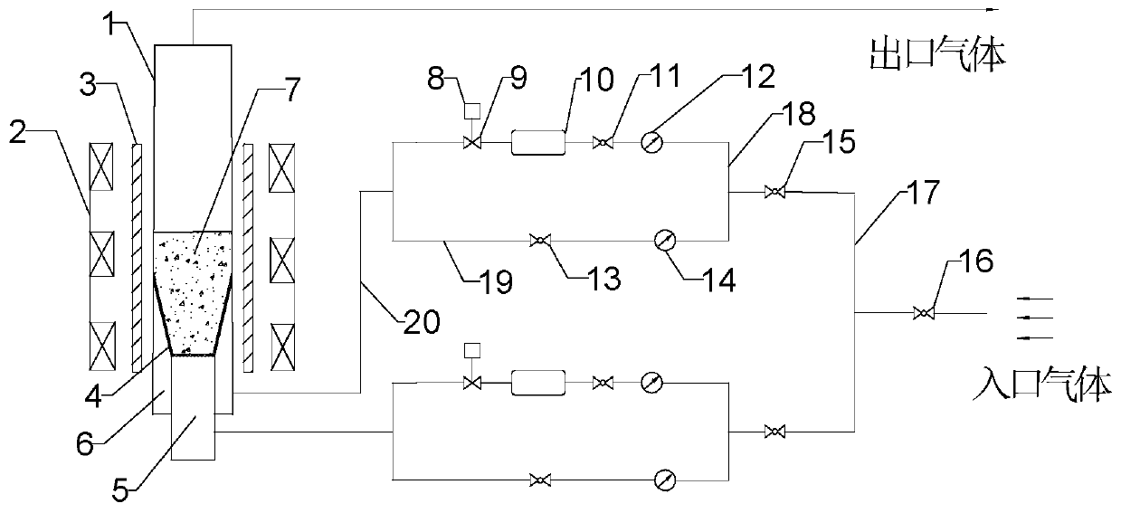
[0033] Specific implementation mode one: combine figure 1To Fig. 2, this embodiment is illustrated, a fluidized bed system of a pulse magnetic combined enhanced methane catalytic reforming hydrogen production in this embodiment, which includes a magnetic fluidized bed reactor and two airflow generating devices, and the magnetic fluidized bed reaction The device includes a fluidized bed reactor 1, a stable magnetic field generator 2, a heater 3, a conical air distribution plate 4, an inner bellows 5, an outer bellows 6 and a bed material layer 7 (referring to the catalyst particle bed material layer), and the fluidized bed The inner side of the lower part of the reactor 1 is provided with a conical air distribution plate 4, the inner bellows 5 is connected to the horizontal section of the conical air distribution plate 4, the lower end of the fluidized bed reactor 1 is provided with an outer bellows 6, and the outer bellows 6 is connected to the conical air distribution plate 4....

specific Embodiment approach 2

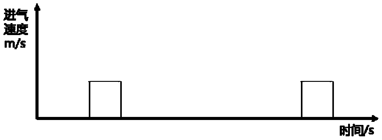
[0036] Specific implementation mode two: combination figure 1 Describe this embodiment, the period of the rectangular wave pulsating air flow of the pulsating air flow generating device of this embodiment is controlled by the solenoid valve 9 and the controller 8, and the controller controls the opening and closing time of the solenoid valve. Such setting makes the frequency of the pulsating airflow more precise and controllable. Other compositions and connections are the same as in the first embodiment.

specific Embodiment approach 3

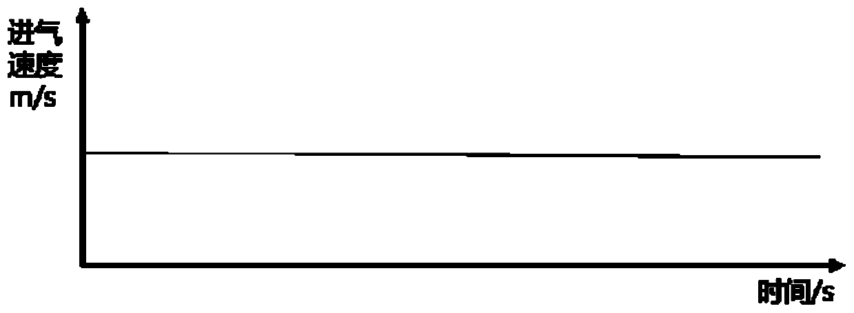
[0037] Specific implementation mode three: combination figure 1 Describe this embodiment, the two airflow generating devices of this embodiment are connected to the inlet gas through the fourth spherical valve 16, and each airflow generating device includes a continuous airflow generator and a rectangular waveform pulsating airflow generator, and a rectangular waveform pulsating airflow generator Including controller 8, solenoid valve 9, gas buffer tank 10, first ball valve 11 and first rotameter 12; continuous flow generator includes second ball valve 13, second rotameter 14 and third ball valve 15 , the first inlet gas pipeline 17 on the air flow generating device is equipped with a third spherical valve 15, the first inlet gas pipeline 17 is provided with a parallel first branch pipeline 18 and a second branch pipeline 19, the first The branch pipeline 18 and the second branch pipeline 19 are connected in parallel to one end of the output gas pipeline 20, and the other end ...


PUM

PropertyMeasurementUnit
particle sizeaaaaaaaaaa
particle diameteraaaaaaaaaa

Abstract

The invention provides a pulsation gas flow and magnetic field combined enhanced methane catalytic reforming hydrogen production system and a pulsation gas flow and magnetic field combined enhanced methane catalytic reforming hydrogen production method, and relates to a fluidized bed methane catalytic reforming hydrogen production system and a fluidized bed methane catalytic reforming hydrogen production method. In the prior art, the utilization efficiency of the catalyst is low, the fluidization quality in the fluidized bed is low, the reaction rate is low, the catalytic reforming hydrogen production reaction-regeneration device is complicated, and other problems exist. A purpose of the present invention is to solve the problems in the prior art. According to the system, the lower portionof a fluidized bed reactor is provided with a conical wind distribution plate, an inner wind box is connected to the horizontal section of the conical wind distribution plate, an outer wind box is connected to the inclined section of the conical wind distribution plate, a heater is installed on the outer portion of the fluidized bed reactor, a stable magnetic field generator is installed on the outer portion of the heater, and the outlets of two independent gas flow generating devices are respectively connected to the inner wind box and the outer wind box. According to the method, the reduction of catalyst particles is firstly performed, than a catalytic reforming hydrogen production reaction is performed, and finally a coke deposition removing reaction is performed on the catalyst. The system and the method of the present invention are used for methane catalytic reforming hydrogen production.

Description

technical field [0001] The invention relates to a fluidized bed reactor and method for hydrogen production by catalytic reforming of methane, in particular to a device and method for integrating catalytic reforming reaction of methane with pulsating gas flow coupling magnetic field and catalyst regeneration reaction. Background technique [0002] As a clean energy, hydrogen is gradually playing an important role on the world energy stage. It has the advantages of high combustion calorific value, good combustion performance, multiple utilization forms, and multiple storage methods. It is widely used in petroleum, chemical, aerospace, Medicine, metallurgy and other fields. With the deepening of the emphasis on environmental issues, my country has gradually raised the emission standards of pollutants such as nitrogen oxides and sulfur oxides released by primary energy combustion in recent years, and the demand for hydrogen in my country has also gradually increased. Methane st...

Claims


Application Information

Patent Timeline
Patent Type & Authority Applications(China)
IPC IPC(8): C01B3/44
Inventor 王帅章凯杨学松胡棒何玉荣
Owner HARBIN INST OF TECH
Why Eureka
Try Eureka