Metal material crack type defect depth measuring device and method

A metal material, defect depth technology, applied in the direction of measuring devices, using sound waves/ultrasonic waves/infrasonic waves to analyze solids, instruments, etc., can solve the problems of low sensitivity of plane defects, complex detection system, stress concentration, etc., to achieve simple equipment and operation, The effect of simple signal processing and high sensitivity

Inactive Publication Date: 2019-05-10
UNIV OF SCI & TECH BEIJING
View PDF7 Cites 11 Cited by
  • Summary
  • Abstract
  • Description
  • Claims
  • Application Information

AI Technical Summary

Problems solved by technology

[0002] Crack is a dangerous defect, which not only seriously weakens the bearing capacity and corrosion resistance of the workpiece, but also easily causes stress concentration at the end of the crack, which becomes the source of various fractures
In actual testing, cracks often appear at the discontinuity of workpiece geometry, structure and load, such as weld fusion line, heat-affected zone, etc. The application of penetration and magnetic particle testing methods can effectively find surface cracks and measure their length, but the depth It is difficult to measure, and ray detection has high sensitivity to volume defects and low sensitivity to planar defects. It is difficult to detect when the crack is not completely parallel to the direction of the ray
[0003] At present, ultrasonic detection technology is an important technical means for quantitative measurement of crack depth, mainly including endpoint diffraction method, creeping wave detection method, diffraction time-of-flight method, phased array detection method, etc. These detection methods are often difficult to achieve depths less than Quantitative detection of 1mm crack-type defects, or the detection system is too complicated to carry out online detection

Method used


Image

  • Metal material crack type defect depth measuring device and method
  • Metal material crack type defect depth measuring device and method
  • Metal material crack type defect depth measuring device and method

Examples


Embodiment Construction

[0020] Exemplary embodiments of the present invention will be described below with reference to the accompanying drawings.

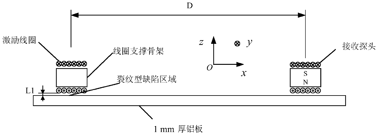
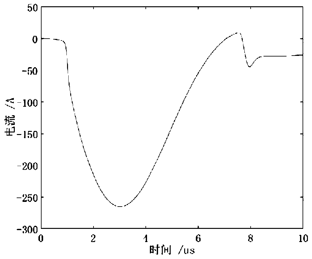
[0021] The sample to be tested is an aluminum plate with a thickness of 1 mm, so there is only a Lorentz force mechanism in the excitation process, and the receiving transducer uses an electromagnetic ultrasonic transducer based on the Lorentz force mechanism. Implementation structure such as figure 2 As shown, the excitation coil adopts 6 turns of rectangular coil with a diameter of 1mm, and the coil is made of enameled copper wire; the dimensions of the coil along the y-direction and z-direction are 30mm and 15mm, respectively, and the axial direction of the coil is parallel to the x-axis. Lifting distance L of excitation coil 1 =1mm; the pulse current passed into the excitation coil is such as image 3 As shown, the maximum current is about 270A, and the pulse duration is about 7 μs. The receiving probe adopts an electromagnetic ultrasonic transdu...


PUM

PropertyMeasurementUnit
thicknessaaaaaaaaaa
diameteraaaaaaaaaa

Abstract

The invention discloses a metal material crack type defect depth measuring device and method. A pulse generator (1) emits a pulse signal to drive a multi-turn coil (2) to generate ultrasonic waves ina metal sample (4) based on a Lorentz force mechanism, a receiving probe (3) receives the ultrasonic waves and converts same into an electrical signal, the electrical signal is amplified by a signal amplifier (5), and the peak-to-peak value of the ultrasonic waves is recorded by a signal recording and analyzing module (6). The method comprises the following steps: in a calibration stage, measuringthe standard sample without defects, recording the peak-to-peak value of the S0 Lamb wave as A0, artificially fabricating grooves of different depths h on the standard sample to obtain the peak-to-peak value Ah of the S0 Lamb wave when the depth of the groove is h, calculating the enhancement coefficient E=Ah / A0 of the S0 Lamb wave, and plotting a (h, E) graph; and in an actual measurement stage,using the metal material to be tested as the metal sample (4), obtaining the peak-to-peak value of the S0 Lamb wave as Ad, calculating E=Ad / A0, and obtaining the depth h of the crack type defect by the (h, E) graph.

Description

technical field [0001] The invention relates to electromagnetic ultrasonic nondestructive testing technology, in particular to a method of exciting ultrasonic waves in metal materials through a Lorentz force mechanism. The increase in amplitude is called near-field enhancement. The relationship between the enhancement coefficient of S0 Lamb wave and the depth of crack-type defects is used to carry out non-destructive testing of the depth of crack-type defects in metal materials. Background technique [0002] Crack is a dangerous defect, which not only seriously weakens the bearing capacity and corrosion resistance of the workpiece, but also easily causes stress concentration at the end of the crack, which becomes the source of various fractures. In actual inspection, cracks often appear in the workpiece geometry, structure and load discontinuity, such as weld fusion line, heat affected zone, etc. The application of penetration and magnetic particle inspection methods can eff...

Claims


Application Information

Patent Timeline
Patent Type & Authority Applications(China)
IPC IPC(8): G01B17/00G01N29/04
Inventor 徐科张初周鹏任威平
Owner UNIV OF SCI & TECH BEIJING
Why Eureka
Try Eureka