
High-temperature waste heat recovery system adopting two-roller method

A waste heat recovery system and technology of waste heat recovery, applied in waste heat treatment, energy efficiency improvement, lighting and heating equipment, etc., can solve the problems of large power consumption, large equipment size, high operating cost, etc., achieve high waste heat recovery efficiency, realize cascade Utilization, wide range of application effects

Pending Publication Date: 2019-05-14
XI AN JIAOTONG UNIV
View PDF0 Cites 6 Cited by
  • Summary
  • Abstract
  • Description
  • Claims
  • Application Information

AI Technical Summary

Problems solved by technology

Among them, the wind quenching method consumes a lot of power during the granulation process, and the cooling rate is very slow compared with water quenching. In order to prevent the particles from adhering to the surface of the equipment before solidification, a large equipment size is required
The centrifugal granulation method can make the particle size reach about 2mm, but the granulation effect is poor in the case of high viscosity, and it is difficult to achieve sufficient solidification of the particles before hitting the outer wall, which has similar problems to the wind quenching method
[0004] In the double-roller method, the molten material adheres to the surface of the roller to form a thin liquid film. Through the heat conduction to the cooling roller and the radiation of the film wall, the rapid reduction of temperature, solidification and heat recovery are realized. The processing capacity is much larger than that of Wind quenching method and centrifugal granulation method, and the working condition of the system is less affected by the physical properties of the melt, but in the actual application process, there are disadvantages such as low heat energy recovery rate and high operating cost

Method used


Image

  • High-temperature waste heat recovery system adopting two-roller method
  • High-temperature waste heat recovery system adopting two-roller method

Examples


Embodiment Construction

[0025] The present invention will be described in further detail below in conjunction with the accompanying drawings.

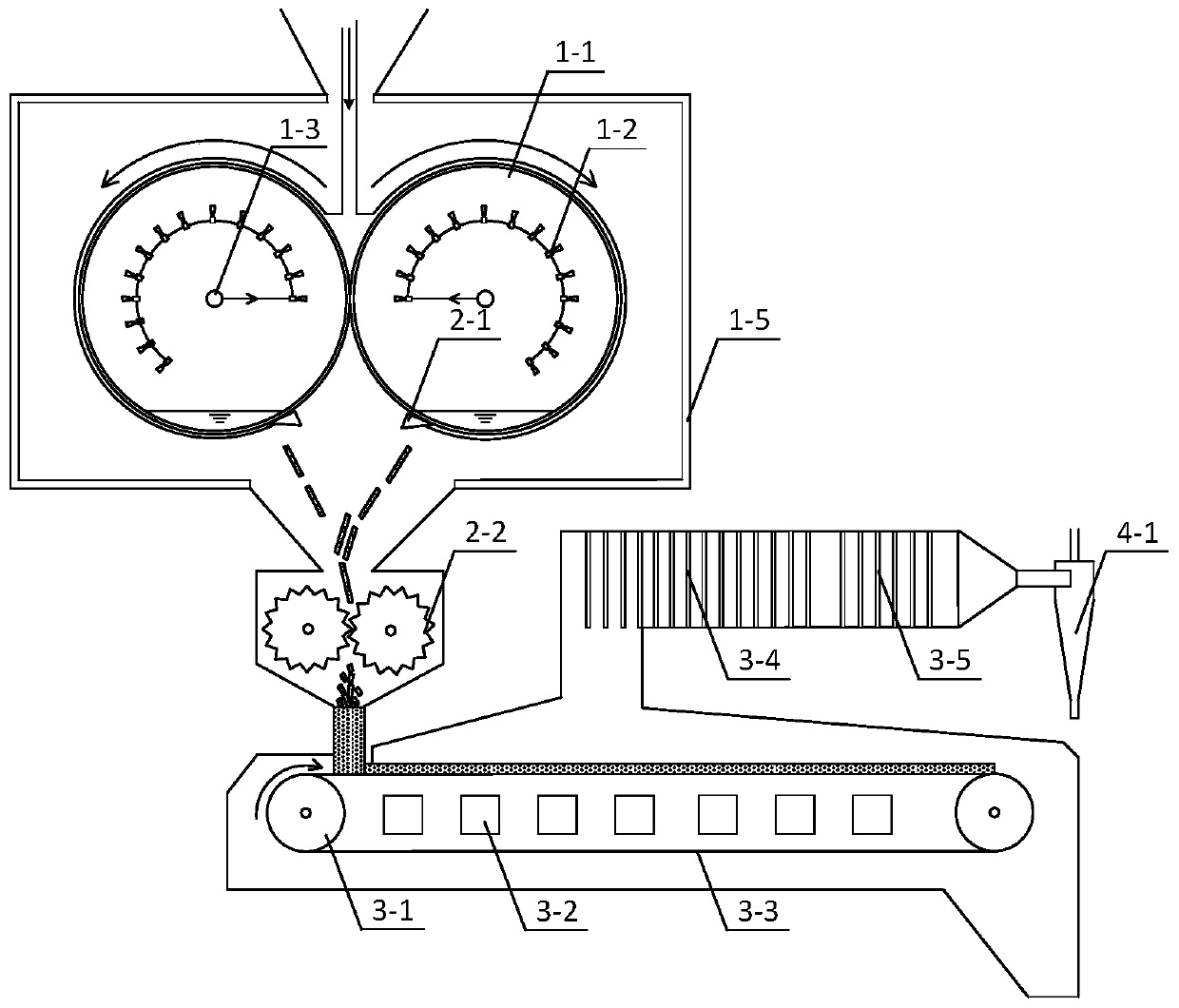
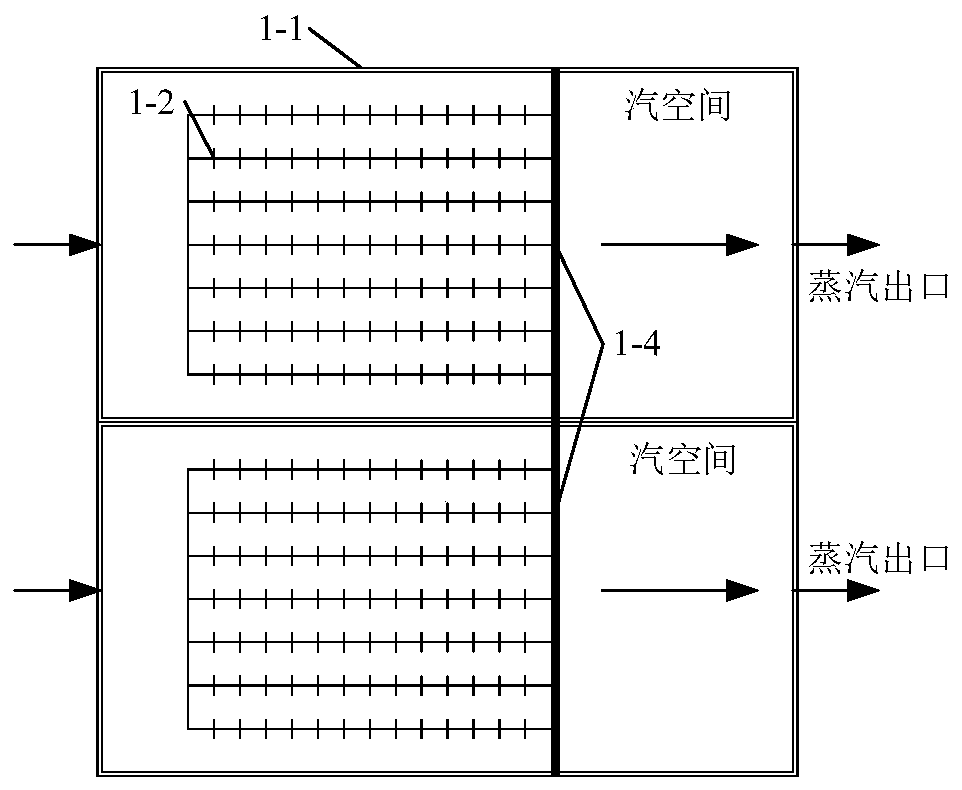
[0026] Such as figure 1 with figure 2 As shown, the present invention provides a double-roller high-temperature waste heat recovery system, including a cooling and solidification unit, a peeling and crushing unit, a moving bed waste heat recovery and utilization unit, and a gas purification unit.

[0027] Among them, the cooling and solidification unit uses heat exchange media to realize the solidification and heat recovery of high-temperature molten materials; the stripping and crushing unit is used to scrape off the solidified solids formed by the cooling and solidification unit, and further break them into smaller solid particles; the moving bed waste heat recovery The utilization unit is used to convey the crushed solid particles, and the air is continuously introduced during the process, and finally the solid particles are cooled to below 200 °C, and a...


PUM


Abstract

The invention discloses a high-temperature waste heat recovery system adopting a two-roller method. The high-temperature waste heat recovery system is composed of a cooling solidification unit, a peeling and crushing unit, a moving bed waste heat recycling unit and a gas purification unit. The high-temperature waste heat recovery system has the effects that industrial high-temperature waste heat is efficiently utilized, and a product is formed while high waste heat recovery efficiency and system flexibility and the high cooling speed are guaranteed; the double-roller method and a moving bed waste heat recycling device are combined, compared with a traditional waste heat recovery technology adopting the two-roller method, the temperature of the final product can be significantly decreased,and the utilization efficiency of heat energy is improved; a crusher is additionally arranged, and thus under the premise of guaranteeing the heat exchange efficiency of a moving bed, the product is crushed to be formed; and the gas purification unit is additionally arranged, and thus particulate matter in exhaust gas is removed.

Description

technical field [0001] The invention belongs to the technical field of dry recovery of high-temperature industrial waste heat, and in particular relates to a double-roller high-temperature waste heat recovery system. Background technique [0002] At present, there is still a large amount of high-grade waste heat that has not been rationally utilized in some high-energy-consuming industrial fields, such as blast furnace slag and steel slag in the iron and steel industry, and molten calcium carbide in the production process of calcium carbide. Among them, the temperature of high-temperature slag is mostly around 1500°C, and the temperature of calcium carbide just out of the furnace can even be as high as 2000°C. The use of natural cooling takes a long time, occupies a large area and causes a lot of waste of heat energy. Although the commonly used water quenching technology can achieve rapid cooling, the low-grade heat generated cannot be recycled. [0003] In order to avoid t...

Claims


Application Information

Patent Timeline
IPC IPC(8): C21B3/08C01B32/942F27D17/00
CPCY02P20/129Y02P10/25Y02P20/10
Inventor 刘虎于鹏飞周赛史晓云支小强车得福邓磊
Owner XI AN JIAOTONG UNIV
Learn More