
High-humidity flue gas particle sampling and measuring device and use method thereof

A measuring device and flue gas technology, applied in the direction of measuring device, sampling device, particle and sedimentation analysis, etc., can solve the problems of measurement and analysis of particle size characteristics of inapplicable particles, large error in sample collection, limited dehumidification capacity, etc., to achieve Improved dehumidification performance, easy operation, and strong practicality

Inactive Publication Date: 2019-05-17
XI AN JIAOTONG UNIV
View PDF16 Cites 4 Cited by
  • Summary
  • Abstract
  • Description
  • Claims
  • Application Information

AI Technical Summary

Problems solved by technology

This invention dehumidifies high-humidity flue gas through the gas-liquid cyclone separator placed at the front end of the sampling gun and the nafion tube bundle used in the sampling gun barrel, but the gas-liquid cyclone separator used in this invention is likely to cause mis-separation of particles during the working process , the sample collection error is relatively large, it is not suitable for the measurement and analysis of particle size characteristics, and the flue gas of this invention is diluted with gas to reduce the proportion of moisture content after being bundled by nafion tubes, and the dehumidification capacity is limited

Method used


Image

  • High-humidity flue gas particle sampling and measuring device and use method thereof
  • High-humidity flue gas particle sampling and measuring device and use method thereof
  • High-humidity flue gas particle sampling and measuring device and use method thereof

Examples


Embodiment Construction

[0039] The present invention will be described in further detail below in conjunction with accompanying drawing and specific embodiment, and its content is explanation of the present invention rather than limitation:

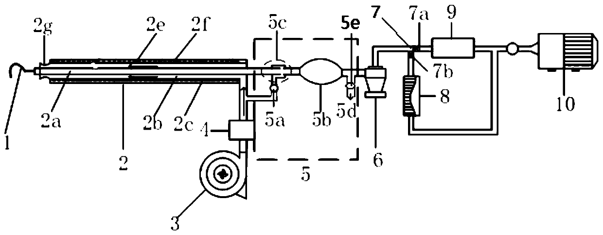
[0040] figure 1It is a schematic diagram of the overall structure of the present invention, which is suitable for particle sampling and measurement of high-humidity flue gas, mainly including: flue gas sampling gun head 1, high-humidity flue gas dehumidification device 2, blower 3, air dryer 4, flue gas dilution device 5. Cyclone separator 6, tee 7, first branch valve 7a, second branch valve 7b, particle sampling device 8, particle size measuring device 9, vacuum pump 10, and press figure 1 Connect sequentially.

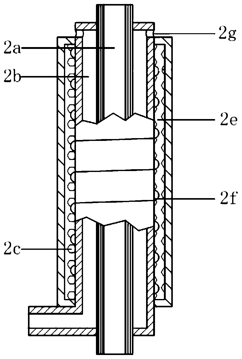
[0041] The high-humidity flue gas dehumidification device such as figure 2 As shown, the whole is a casing structure, which is divided into the first chamber in the flue gas pipe 2a, the second chamber formed by the flue gas pipe 2a and the dry air ...


PUM


Abstract

The invention discloses a high-humidity flue gas particle sampling and measuring device and a use method thereof, and belongs to the technical field of flue gas particle matter sampling and measuring.The high-humidity flue gas particle sampling and measuring device includes a high-humidity flue gas dehumidification device, a flue gas dilution device, a particle separation device, a sampling and measuring device and a vacuum pump; a flue gas tube made from an ion exchange membrane is adopted, the selective permeability of the flue gas tube to water is used for conducting primary dehumidification, a heating device is arranged on the outer wall of a dry air convection tube, the temperature of flue gas is increased, and the flue gas is subjected to secondary dehumidification; external dry airis introduced to the high-humidity flue gas particle sampling and measuring device, introduction of the dry air facilitates outflow of escaping moisture, the concentration difference of the moistureon the two sides of the flue gas tube is increased, and the dehumidification ability is improved; and meanwhile, the flue gas with the increased concentration after dehumidification is diluted by arranging the flue gas dilution device and the particle separation device, and meanwhile, large particles of a non-test target are removed to meet the requirements of subsequent sampling and measuring. The high-humidity flue gas particle sampling and measuring device has reasonable structure design, convenient operation and accurate measuring values.

Description

technical field [0001] The invention belongs to the technical field of smoke particle sampling and measurement, and in particular relates to a high-humidity smoke particle sampling and measuring device and a use method thereof. Background technique [0002] PM2.5 in the air not only aggravates the smog weather, but also because of its small particle size and long residence time in the air, it is very easy to combine toxic substances in the air, when it enters the human blood circulation with breathing , will bring great harm to human health and increase the risk of disease. In recent years, with the increasing smog weather, atmospheric particulate matter pollution has become a hot topic in society. At present, my country has comprehensively carried out the measurement of atmospheric particulate matter to effectively control the emission of smoke particulate matter and other atmospheric particulate matter. [0003] According to relevant research, it is found that the flue ga...

Claims


Application Information

Patent Timeline
IPC IPC(8): G01N1/24G01N1/34G01N1/38G01N1/44G01N15/02
Inventor 杨富鑫李正鸿刘鹤欣谭厚章
Owner XI AN JIAOTONG UNIV
Learn More