Heat energy storage and release system based on tubular heating furnace

A tubular heating furnace and thermal energy storage technology, which is applied to lighting and heating equipment, furnaces, waste heat treatment, etc., can solve the problems of high utilization cost, limited use scale and scope, endangering the stable operation of equipment and systems, and achieve land saving Cost of use, flexible and convenient system design, and significant economic value

A tubular heating furnace and thermal energy storage technology, which is applied to lighting and heating equipment, furnaces, waste heat treatment, etc., can solve the problems of high utilization cost, limited use scale and scope, endangering the stable operation of equipment and systems, and achieve land saving Cost of use, flexible and convenient system design, and significant economic value

CN109780877APending Publication Date: 2019-05-21BEIJING PIONEER IND FURNACE

Image

  • Heat energy storage and release system based on tubular heating furnace

Examples


Embodiment Construction

[0019] The present invention will be described in detail below with reference to the drawings and embodiments.

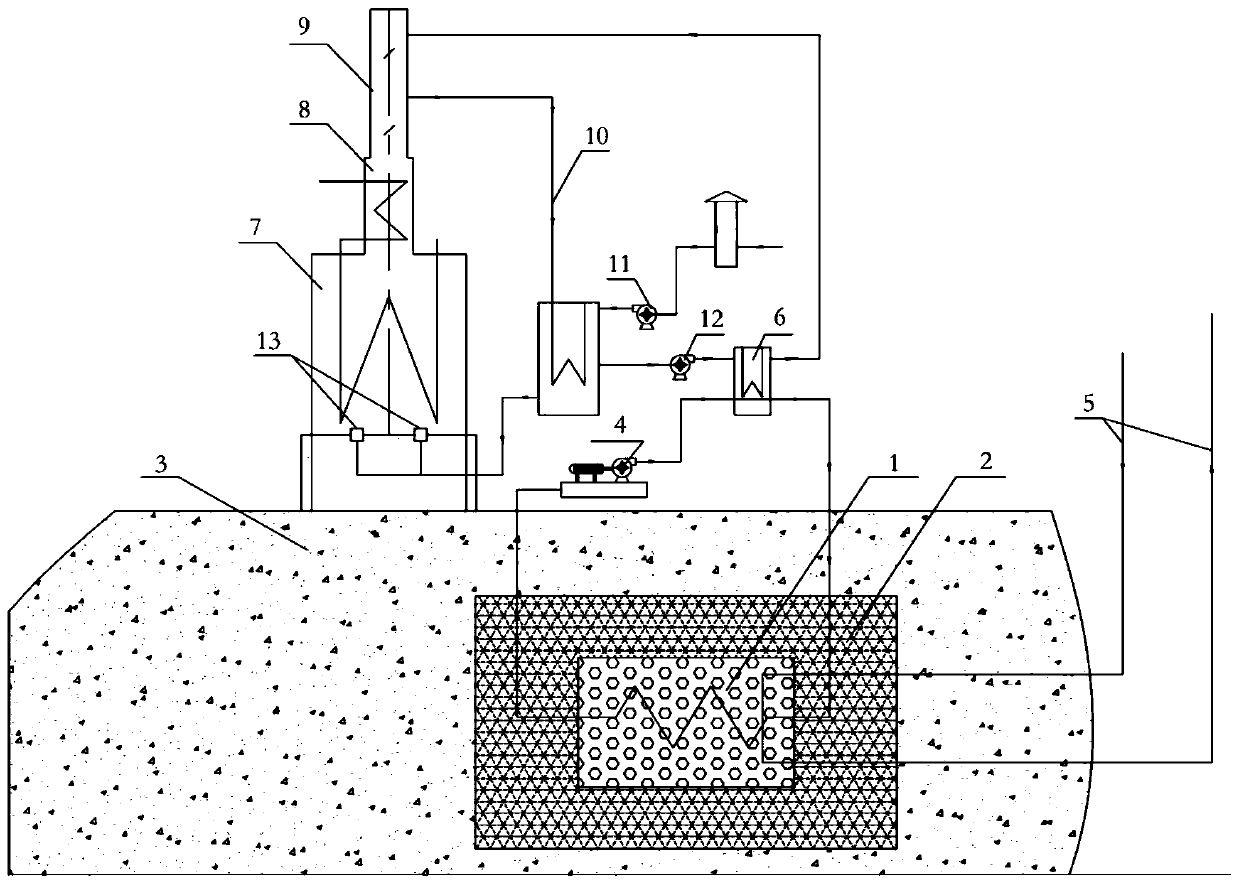
[0020] As attached figure 1 As shown, the present invention provides a thermal energy storage and release system based on a tube heating furnace. The thermal energy storage and release system is connected to the flue gas pipe 10 in the tube heating furnace, and the flue gas of the tube heating furnace is realized through heat exchange. The storage of thermal energy.

[0021] In the tubular heating furnace, the combustion unit 13 heats the equipment in the radiation chamber 7, and the high-temperature flue gas generated by the fuel flows into the chimney 9 from the convection chamber 8 above the radiation chamber, and the flue gas pipe 10 leads the high-temperature flue gas from the chimney In the air preheater, the outside air drawn by the air blower exchanges heat with the high-temperature flue gas in the air preheater and enters the radiation chamber 7 to participate ...


PUM


Abstract

The invention discloses a heat energy storage and release system based on a tubular heating furnace. The heat energy storage and release system comprises a phase change heat storage material, a heat preservation layer, an energy storage medium circulating unit, an energy storage outer conveying pipeline and an energy storage outer heat collector. The heat preservation layer is arranged in an energy storage tank excavated in soil. The phase change heat storage material is completely wrapped with the heat preservation layer. Positions above the heat preservation layer are backfilled with soil. The energy storage medium circulating unit is connected with the phase change heat storage material and the energy storage outer heat collector connected in a flue gas pipeline of the tubular heating furnace at the same time. Heat energy in the flue gas pipeline is stored in the phase change heat storage material after being subjected to heat exchange with the phase change heat storage material. The energy storage outer conveying pipeline is connected with the phase change heat storage material at the same time. The heat energy stored in the phase change heat storage material is released outwards through the energy storage outer conveying pipeline when needed. By means of the heat energy storage and release system, waste heat of the tubular heating furnace can be stably stored in a centralized manner, device energy consumption and the production cost are reduced, and climate change caused by greenhouse gas emission is reduced to the maximum extent.

Description

Technical field [0001] The invention relates to an energy storage system for a tubular heating furnace, and belongs to the technical field of petrochemical heating tubular heating furnace equipment. Background technique [0002] Tubular heating furnace is a process heating furnace used in petroleum refining, petrochemical and chemical, chemical fiber industry, coal chemical industry, and coal-to-liquid. The heated material flows in the tube, but gas, liquid, and gas, liquid, and solid particles containing solid particles. Phase medium. Moreover, these media are flammable and explosive substances, which are dangerous [0003] The energy consumption of the tube heating furnace occupies a considerable proportion in the device, and can reach 90% at the maximum. Thermal efficiency is an important indicator of the advanced nature of tubular heating furnaces. Affected by the processing technology and cold source medium, the heating furnace is generally equipped with an air preheater, wh...

Claims


Application Information

Patent Timeline
21 May 2019
Publication
CN109780877A
IPC
F27D17/00; F28D20/02; F23L15/04
CPC
Y02E20/34; Y02E60/14; Y02P10/25
Inventors
王扬; 张宁博