A construction method for drilling holes in earthwork below highway drainage ditches

A construction method and drainage ditch technology, applied in the field of road drainage engineering, can solve problems such as road subsidence, hole collapse, failure to meet construction requirements, etc., and achieve the effects of high molding quality, easy implementation, and flexible and ingenious design.

Active Publication Date: 2020-10-13
CHINA MCC5 GROUP CORP +1
View PDF5 Cites 0 Cited by
  • Summary
  • Abstract
  • Description
  • Claims
  • Application Information

AI Technical Summary

Problems solved by technology

[0003] For the underground ditch (pipe) construction process in underground drainage facilities, it is necessary to penetrate the drainage hole from the bottom of the drainage ditch to the other side of the road. In this drilling process, the traditional construction method is directly through hydraulic devices or other mechanical equipment. Drainage holes are drilled, but for some working conditions with a lot of water in the subgrade, if the hole is drilled directly, it is easy to cause the hole to collapse, or even directly lead to the subsidence of the road surface, which does not meet the construction requirements. Drain hole drilling construction method

Method used


Image

  • A construction method for drilling holes in earthwork below highway drainage ditches
  • A construction method for drilling holes in earthwork below highway drainage ditches
  • A construction method for drilling holes in earthwork below highway drainage ditches

Examples


Embodiment 1

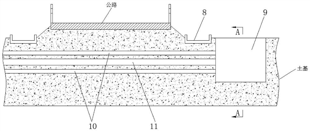
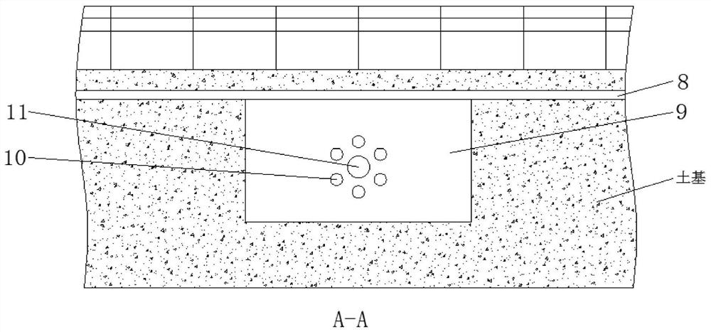
[0033] Such as Figures 1 to 5 As shown, the present embodiment provides a construction method for earthwork perforation below the highway drainage ditch, comprising the following steps:

[0034] Step 1: Excavate the foundation pit 9 on one side of the drainage ditch 8;

[0035] Step 2: In the foundation pit 9, drill a number of reinforcement holes 10 uniformly distributed in a circular array on the side of the foundation pit 9 through the guide pier and drilling equipment. After the reinforcement hole 10 of height, to reinforcement hole 10 internal pumping, until water level drops below reinforcement hole 10, then reinforcement hole 10 is grouted, after the cement slurry in reinforcement hole 10 is solidified, plan the soil foundation at the bottom of guide pier, until The height of the guide pier is lowered to a suitable position, and then a reinforcement hole 10 of the next height is drilled through the guide pier, and the above operation is repeated to perform pumping and...

Embodiment 2

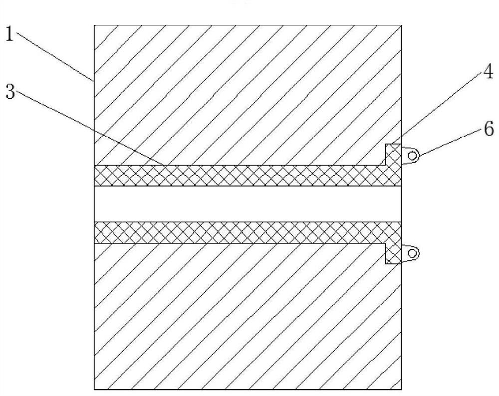
[0043] Such as Figures 3 to 5 As shown, the present embodiment is further optimized on the basis of Embodiment 1. Specifically, the guide pier includes a pier body 1, and a number of evenly distributed guide holes 2 of equal height are provided inside the pier body 1. The holes 2 are all provided with an adjusting sleeve 3 that cooperates with the guide hole 2, and one end of the adjusting sleeve 3 is provided with a number of outwardly protruding blocks 4, and the plurality of blocks 4 are arranged in a circular array with the center of the guide hole 2 as the center of the circle. The side of the pier body 1 is provided with a number of slots 5 that cooperate with the blocks 4, and the slots 5 communicate with the guide holes 2.

[0044] In this embodiment, when using the guide pier, the diameter of the guide hole is limited by adjusting the sleeve, and the inner diameter of the adjustment sleeve matches the diameter of the drill pipe in the drilling equipment. , select th...

Embodiment 3

[0046] Such as Figures 3 to 5 As shown, this embodiment is further optimized on the basis of embodiment 2. Specifically, the pier body 1 is square as a whole, and the pier body 1 is made of concrete, which has low manufacturing difficulty and low manufacturing cost.

[0047] The clamping block 4 and the adjusting sleeve 3 are integrally formed or welded, which is convenient for processing and has low manufacturing difficulty. The materials of the clamping block 4 and the adjusting sleeve 3 are both steel or iron, which meet the requirements for use strength. The number of 4 is 3-6, satisfying the stability of the clamping structure.

[0048] The outside of the clamping block 4 is connected with a lifting lug 6, and one clamping block 4 is only connected to one lifting lug 6, and there are at least two lifting lugs 6. After use, the lifting lug 6 is hung on a hook, and the other end of the hook passes through The zipper is connected to a mechanical device (such as a trailer),...


PUM


Abstract

The invention discloses a drilling method of earth below highway ditches and relates to the technical field of highway drainage engineering. The drilling method herein comprises the steps of digging afoundation pit on one side of a ditch, drilling a plurality of circularly arrayed and evenly distributed reinforcing holes in the lateral side of the foundation pit in the foundation pit through guide piers and a drilling apparatus in a sequence of from top to bottom, after the reinforcing holes of same height are made, draining the reinforcing holes until the water level drops below the reinforcing holes, grouting the reinforcing holes, after cement grout in the reinforcing holes sets, removing earth bases at the bottom of the guide piers until the heights of the guide piers decrease to a suitable level, drilling reinforcing holes of next height through the guide piers, repeatedly the operation above to drain and grout the reinforcing holes of the height, and after the cement grout in the reinforcing holes of the smallest height sets, and drilling a drain hole in the center of a circular array formed by the reinforcing holes. The drilling method herein has the advantages that construction is reasonable and the drain holes can prevent pavement sinking.

Description

technical field [0001] The invention relates to the technical field of road drainage engineering, and more specifically relates to a construction method for drilling holes in the earth below a road drainage ditch. Background technique [0002] In highway construction, the strength and stability of subgrade and pavement are closely related to water. There are many kinds of diseases of subgrade and pavement, and there are many factors that form diseases, but the effect of water is one of the main factors. Roadbed subsidence, scour, collapse, muddying, loose asphalt pavement, peeling, cracking, cement concrete pavement mud, dislocation, fracture and other diseases are all related to the erosion of surface water and groundwater to varying degrees. The damage of pavement and pavement structure accelerates the deterioration of pavement performance and shortens their service life. Therefore, in the design, construction and maintenance of roadbed and pavement, great attention must b...

Claims


Application Information

Patent Timeline
Patent Type & Authority Patents(China)
IPC IPC(8): E02D3/10E02D15/04E01C3/04
Inventor 杨永红邓安彭涛付代准王安亮
Owner CHINA MCC5 GROUP CORP
Why Eureka
Try Eureka