High-fidelity array processing broadband time delay estimation method

A technology of array processing and time delay estimation, applied in radio wave measurement systems, instruments, etc., can solve the problems that the unique identification of parameter estimation cannot be guaranteed, cannot be solved, and the amount of calculation is large.

Active Publication Date: 2019-05-24
SOUTHEAST UNIV
View PDF6 Cites 12 Cited by
  • Summary
  • Abstract
  • Description
  • Claims
  • Application Information

AI Technical Summary

Problems solved by technology

Self-calibration algorithm Due to the coupling between the position error of the array element and the orientation parameter and some ill-conditioned array structures, the unique identification of the parameter estimation is often not guaranteed. What is more important is the high-dimensional, multi-mode nonlinear optimization corresponding to the joint estimation of the parameters. The problem brings a huge amount of computation, and the estimated global convergence is often not guaranteed
(2) Focused beamforming: Spherical wave compensation is performed on the delay difference according to different azimuths and distances in the measurement area, and the distribution map of the target sound source in the measurement area is obtained to achieve high-precision passive positioning of near-field targets. According to the estimated target The distance and azimuth use conventional spherical wave beamforming to reconstruct the source signal with high fidelity. This technology is simple in principle and easy to implement. It can effectively solve the problem of time delay mismatch between array elements caused by the assumption of plane waves under near-field source conditions, but the computational complexity is large. And it can't solve the delay mismatch caused by the position error of the array element (3) ESPRIT (estimate signal parameters by means of rotation invariance) super-resolution direction finding: use the translation invariance of the array to estimate parameters, and obtain signals directly through eigenvalues parameters, this method does not need to search for spectral peaks with a huge amount of calculations, and does not need to store the array popular matrix, but requires the array to be known precisely (4) Beamforming with constant beamwidth: select the beamformed on each frequency component within the broadband signal bandwidth The weighted vector makes the array system have the same spatial filtering response to input signals of different frequencies. This technology can eliminate the nonlinear distortion of the tracking beam output signal caused by the target azimuth estimation error, but the calculation is large and cannot solve the Delay mismatch caused by position error, plane wave assumption, and target azimuth estimation error (5) Zero-steering beamforming: adjust the weights so that the array response is 1 in the signal direction and 0 in the interference direction, so as to achieve The purpose of suppressing interference is actually to make the beam pattern form a zero point in the interference direction. This technology plays an important role in eliminating directional interference, but it needs to accurately know the signal and interference orientation and formation information.

Method used


Image

  • High-fidelity array processing broadband time delay estimation method
  • High-fidelity array processing broadband time delay estimation method
  • High-fidelity array processing broadband time delay estimation method

Examples


Embodiment

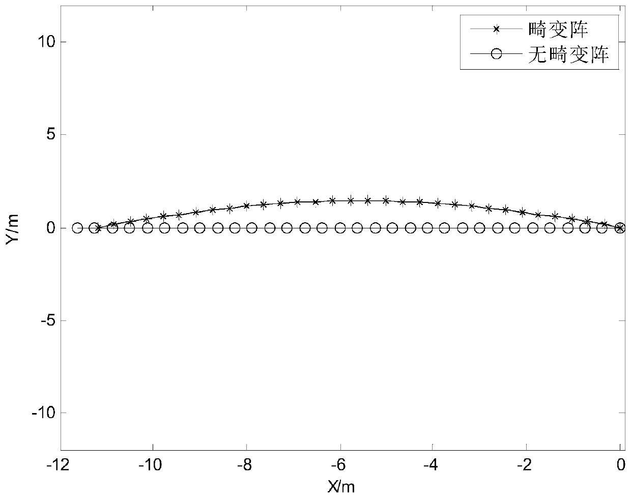
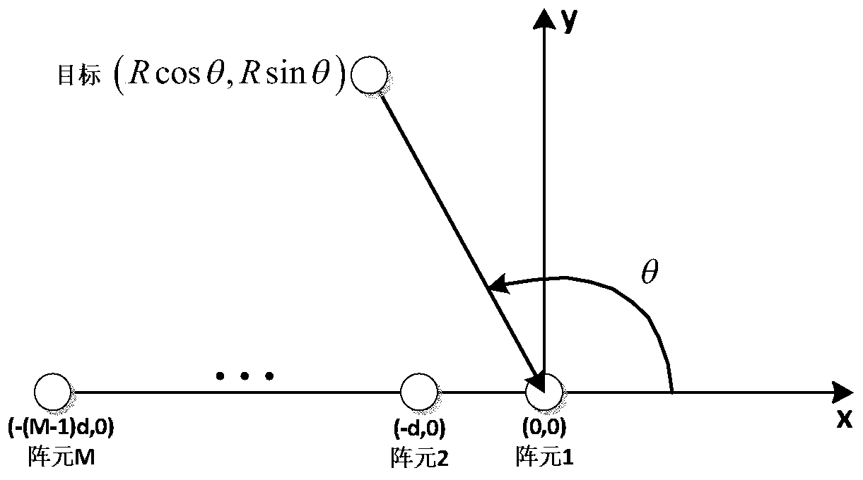
[0166] The simulation signal parameters were set as follows: the number of uniform linear array elements M = 32, the distance between the elements d = 0.375m, the coordinate position of the distortion array and the undistorted array element figure 2 Shown. The coordinate position of the target and the distortionless array element is shown as image 3 As shown, taking the first element of the array head as the coordinate origin, the angle between the target and the direction of the array head is θ=120°, and the distance between the target and the reference array element is R=3000m. Sampling frequency f s = 10kHz, the propagation speed of sound waves in water V = 1500m / s. The signal-to-noise ratio of the data received by the single-array element is -9.62dB, including 100.08Hz, 300.1Hz, 500.2Hz, 800.3Hz, 1000.41Hz, 1200.7Hz, 1500.5Hz, 1801.5Hz, 1999.5Hz, 9 line spectra, long time analysis window When it is 8s, the corresponding frequency domain signal-to-noise ratio is -3dB, 12dB...


PUM


Abstract

The invention discloses a high-fidelity array processing broadband time delay estimation method. The high-fidelity array processing broadband time delay estimation method comprises the following stepsof (1) solving a beam energy diagram, and estimating a target bearing; (2) pre-reconstructing source signals, and detecting the line spectrum position of the power spectrum of the pre-reconstructed source signals; (3) computing the frequency domain signal-to-noise ratio of the frequency line spectrum corresponding to the power spectrum of the collected data of a reference array element; (4) calculating the inter-array-element phase difference of corresponding frequency line spectra; (5) performing weight fusion on the inter-array-element phase difference estimated on the basis of different frequency line spectra to estimate the broadband time delay vectors of target signals; (6) performing secondary reconstruction on the source signals from the collected data of a base array. Based on thefact that the line spectra of different frequencies of the target signals have the same inter-array-element time delay, the high-fidelity array processing broadband time delay estimation method performs weight fusion on the inter-array-element phase differences estimated on the basis of different frequency line spectra according to the frequency and the frequency domain signal-to-noise ratios ofthe line spectra to compute more accurate broadband time delay vectors of the target signals and further to acquire fidelity-enhanced reconstructed source signals.

Description

Technical field [0001] The invention belongs to the field of sonar signal processing, and in particular relates to a wideband time delay estimation method for high-fidelity array processing. Background technique [0002] Classification and recognition of underwater acoustic targets is one of the important topics in underwater acoustic signal processing. For passive sonar target classification and recognition, the key is the feature extraction of target radiated noise. In order to improve the performance of feature extraction, beamforming is an effective method and common method to reconstruct the source signal from the sensor array signal to resist noise and separate multi-target interference in space. However, in the underwater acoustic environment, due to the error of the element position, the assumption of the plane wave, and the estimation error of the target azimuth, it may cause the delay mismatch when the conventional beamforming method tracks the beam output, resulting i...

Claims


Application Information

Patent Timeline
Patent Type & Authority Applications(China)
IPC IPC(8): G01S7/539G01S7/537
Inventor 方世良朱传奇罗昕炜安良
Owner SOUTHEAST UNIV
Why Eureka
Try Eureka