Wave energy conversion device for synchronous belt transmission oscillating floater

A synchronous belt transmission and conversion device technology, applied in the direction of electromechanical devices, motor vehicles, electric components, etc., can solve problems that cannot be solved fundamentally, such as large upward protrusion of the rack, weakening, etc., to improve stability and Anti-wind and wave ability, increase stiffness and strength, and improve the effects of stress conditions

Pending Publication Date: 2019-05-28
闻福三
View PDF9 Cites 5 Cited by
  • Summary
  • Abstract
  • Description
  • Claims
  • Application Information

AI Technical Summary

Problems solved by technology

[0004] The floating body of the above-mentioned wave power generation equipment and the rack and tooth column fixed on the floating body move up and down with the wave. When the wave pushes the float upward, the rack and the tooth column of the rectangular frame will extend upward to the gear (that is, the one-way gear) , when the float reaches the highest point, its protruding height is not less than a wave height; generally, the wave height is about 2 to 3 meters, and this wave height is ideal for power generation, sometimes higher; because at this time, the rack, tooth column, etc. Parts protrude too much from the gear, so the whole device is unstable and the ability to resist wind and waves is weakened
[0005] The guide device for the up and down movement of the oscillating buoy of the above-mentioned wave power generation equipment is realized by the two guide wheels on the buoy and the cooperating column and the tooth column limit wheel. The lateral force, side bending force and torsional force from the wave, There is also the beating force of waves on the sea surface, which acts on the float, gear, rack and tooth column. Due to the weak bearing capacity of this structure, it is easy to be damaged, resulting in the instability of the entire equipment and insufficient wind and wave resistance.
[0006] 2. Chinese invention patent application publication CN 103114958 A discloses a mechanical combined oscillating buoy wave energy generating device, which includes a power generation system and a fixing system; the fixing system includes a buoyancy tank and a fixing frame, and the fixing frame is a cube structure. It is fixedly connected to the top of the floating tank, and the four corners of the side of the fixed frame are respectively equipped with columns; the power generation system is composed of four sets of the same power generation mechanism, and each set of power generation mechanism includes a float, an energy conversion device and an energy output device; The holes are set on the column; the energy conversion device includes a rack fixed on the column and a one-way gear (load gear) fixed on the float; the rack and pinion mechanism converts the linear motion of the float into rotary motion and outputs it to Rotate the generator to complete the conversion from wave energy to electric energy; the device places generators, conversion gears and other mechanism equipment on the oscillating float platform that keeps moving up and down. When the oscillating float is at the lowest point, the column together with the The rack will protrude a very high distance from the gear, causing the entire equipment to be unstable. At the same time, there is also an unstable operating platform and it is very difficult to work on the platform. It is difficult for this device to realize multiple independent buoy power systems through mechanical The shafts are connected in series, thereby reducing the fluctuation of the speed and achieving the purpose of stable power generation
[0007] 3. China Utility Model Patent Authorization Announcement No. CN 201687642 U discloses a marine wave energy power generation device. The device adopts a double-sided rack and pinion mechanism. The rack is fixed on the oscillating float and moves up and down with the oscillating float. Disadvantages brought by the lateral force, the rack chute is designed for the double-sided rack. This measure still cannot solve the problem of the weak ability of the oscillating buoy power generation device to resist wind and waves due to the excessively long upward extension of the rack.
[0008] 4. In the first issue of "Coastal Engineering" magazine published in 2016, the article "Research and Design of Wave Energy Oscillating Float Conversion Experimental Device" disclosed a vertical vibration type oscillating float wave energy power generation system, which is a rack and pinion The typical device of the wave energy conversion method of the transmission oscillating float; the power generation system composed of a single typical device, or the power generation system composed of multiple typical devices, there is a problem that the rack protrudes upwards with the upward movement of the oscillating float, causing instability.
[0009] For the problems of the rack-and-pinion mechanism and the guiding device in the above-mentioned prior art, the resulting oscillation float is unstable in up and down movement, which leads to weakening of the anti-wind and wave ability of the entire power generation device
Although a variety of improvement measures have been adopted, none of them can fundamentally solve the problem

Method used


Image

  • Wave energy conversion device for synchronous belt transmission oscillating floater
  • Wave energy conversion device for synchronous belt transmission oscillating floater
  • Wave energy conversion device for synchronous belt transmission oscillating floater

Examples


Embodiment Construction

[0042] The present invention will be described below in conjunction with the accompanying drawings and examples.

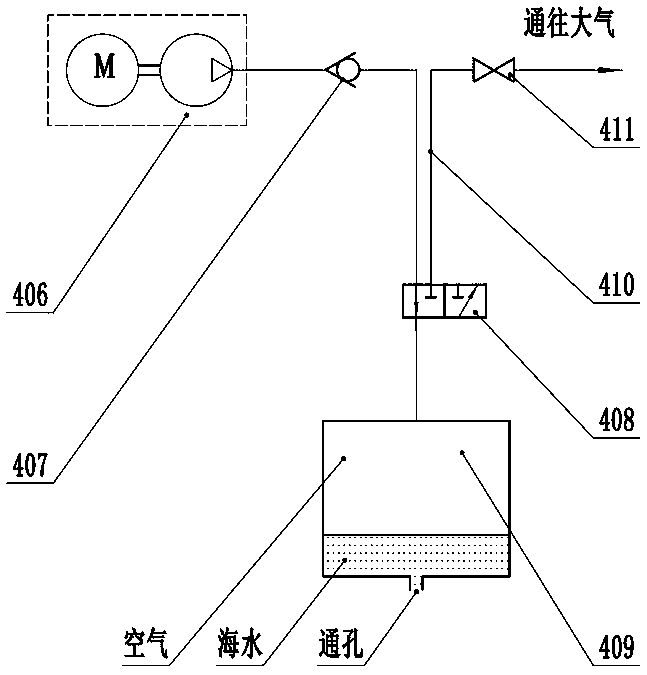
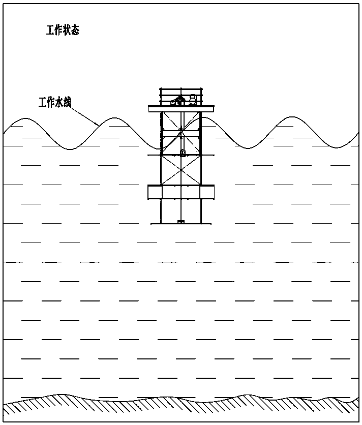
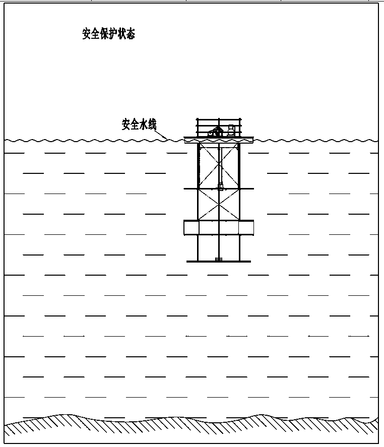
[0043] Such as figure 1 As shown, the synchronous belt drive wave energy conversion device of this embodiment is a power generation device floating on the sea. The floating frame has four parts in total, and all devices are installed and connected as a whole through the truss main body 401 of the floating frame to form a complete device and realize the designed function; among them, the oscillating float I is located on the upper platform of the truss of the floating frame IV In the lower water surface of 402, the mechanical energy conversion device II and the mechanical energy-electrical energy conversion device III are located on the truss upper platform 402 of the floating frame IV.

[0044] Such as figure 2 As shown, the oscillating float includes a wave-absorbing floating body 101, a timing belt fixing device and a guiding device; the wave-absorbing floati...


PUM


Abstract

The invention relates to a wave energy conversion device for a synchronous belt transmission oscillating floater; the wave energy conversion device for the synchronous belt transmission oscillating floater comprises an oscillating floater, an energy conversion device, a floating frame and other parts; the oscillating floater comprises a wave absorbing float body, a synchronous belt fixing device and a guide device; the energy conversion device comprises a synchronous belt transmission device, an overrunning clutch transmission box and a speed increasing transmission, a one-way coupling, a flywheel, a transmission belt and a belt wheel, a generator and an electric control box; the floating frame comprises a truss main body built by rods, a truss platform, a safety floating body, a guide rod, a lifting system and a damping counterweight system; the synchronous belt transmission device comprises a synchronous belt, a synchronous belt wheel, a pinch roller and a synchronous belt tensioningdevice which pass through the middle hole of the wave absorbing floating body; one side of the synchronous belt is fixed with the oscillating floater and converts and outputs kinetic energy of the wave absorbing floating body; the lifting system comprises an air compressor, a control valve, a lifting floating box and a connecting pipeline. The floating energy conversion device is simple in structure, stable and reliable, capable of lifting and resisting strong wind and waves, so the wave energy has high utilization rate.

Description

technical field [0001] The invention relates to an energy conversion device, in particular to an energy conversion device utilizing ocean wave energy, in particular to an energy conversion device for an oscillating buoy driven by a synchronous belt. Background technique [0002] Absorb the energy of the up and down movement of the wave through the oscillating float floating on the water surface, and directly convert the wave energy into mechanical energy that is easy to use, which is high in efficiency, simple and reliable, and has been widely used at present; Only by improving and perfecting can it be better promoted and applied. [0003] 1. Chinese invention patent application publication CN 101900073 A discloses a wave power generation device. The wave power generation device of the invention uses seawater waves to make the floating body (that is, the oscillating float) continuously rise and fall on the diving platform, and the floating body continuously rises and falls...

Claims


Application Information

Patent Timeline
Patent Type & Authority Applications(China)
IPC IPC(8): F03B13/20H02K7/18B63B35/00
CPCY02E10/30
Inventor 李政清闻福三任齐伍时和李社蕾王连胜丁学用赵京明杨泽华葛泽波符永福孙塑埴方蕴赛窦明成王标极刘鹏马晓龙朱承峰肖扬
Owner 闻福三
Why Eureka
Try Eureka