Non-full-coverage coating diaphragm and preparation method and device thereof

A non-full coverage and coating technology, which is applied in the direction of electrical components, electrochemical generators, circuits, etc., can solve the problems of disallowed, damaged, and flat diaphragms, and achieve improved interface consistency, improved cycle life, and glue point distribution uniform effect

Pending Publication Date: 2019-05-28
武汉中兴创新材料技术有限公司
View PDF5 Cites 8 Cited by
  • Summary
  • Abstract
  • Description
  • Claims
  • Application Information

AI Technical Summary

Problems solved by technology

However, the existing non-full-coverage coating preparation methods cannot accurately control the size of each glue point, the distance between the glue points, and the state of agglomeration, so the formed discrete film layer, regardless of the production quality control and subsequent The quality of the coil has an impact
[0004] In order to solve the problem of accurately controlling the size of each glue dot, the distance of glue dots and the state of agglomeration during the diaphragm coating process, some people propose to use traditional printing technology to form a flat, uniform-sized local coating structure; but using traditional printing technology The preparation of non-full coverage coating ignores the technical fact that traditional printing technology can print normally on paper with a thickness of 60-300μm, while the thickness of the separator is usually only 5-25μm; Technology can easily lead to deformation, wrinkling and breakage of the diaphragm during the coating process, these defects are not allowed for the diaphragm
[0005] Therefore, there is currently no non-full-coverage coated separator product with a flat-shaped, uniform-sized, and evenly distributed non-full-coverage coating

Method used


Image

  • Non-full-coverage coating diaphragm and preparation method and device thereof
  • Non-full-coverage coating diaphragm and preparation method and device thereof
  • Non-full-coverage coating diaphragm and preparation method and device thereof

Examples


Embodiment 1

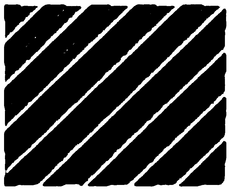
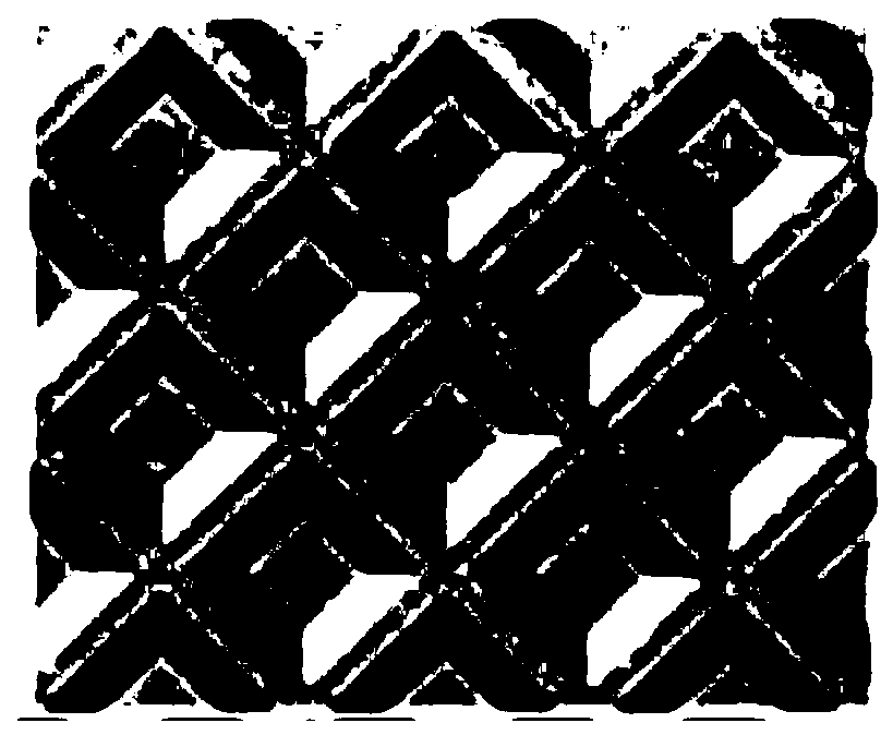
[0047] The device used in this example to prepare a non-full coverage coating membrane includes a micro-grooved roll with improved structure, and the micro-grooved roll adopts a similar figure 2 The discontinuous texture structure shown, the difference is that the mesh of this example is circular; and, in the dimpled roller of this example, the single mesh area of ​​the discontinuous texture structure is 250000μm 2 , the mesh wall width is 70 μm, and the mesh depth is 200 μm. The rest of the device is the same as the existing micro-gravure roller coating device, so it will not be repeated here.

[0048] Based on the preparation device of the non-full coverage coating diaphragm of this example, the preparation method of the non-full coverage coating diaphragm of this example specifically includes the following steps:

[0049] Preparation of coating slurry: Add 40g of polyvinyl alcohol to 200g of deionized water, mix and stir until completely dissolved, then add 100g of vinyli...

Embodiment 2

[0053] In this example, the device and method of the same improved micro-gravure roll as in Example 1 were used to prepare a non-full coverage coating separator. The difference is that the coating slurry formulation in this example is different, and the base film is also different, as follows :

[0054] Coating slurry: Add 40 g of polymethyl methacrylate to 200 g of deionized water, mix and stir until completely dissolved, then add 100 g of alumina powder, and stir at room temperature to make an aqueous slurry.

[0055] Using the same method as in Example 1, the coating slurry is coated on one surface of a 25 μm thick polyethylene terephthalate porous base film to obtain the non-full coverage coating separator of this example, the total coating amount 0.5g / m 2 , the coating thickness is 2.1 μm.

[0056] Among them, the 25 μm thick polyethylene terephthalate porous base film is a self-made base film with a porosity of 65% and a Gurley value of 25s / 100cc.


PUM

PropertyMeasurementUnit
thicknessaaaaaaaaaa
areaaaaaaaaaaa
widthaaaaaaaaaa

Abstract

The invention discloses a non-full-coverage coating diaphragm as well as a preparation method and a preparation device thereof. The non-full-coverage coating membrane comprises a base membrane and a non-full-coverage coating coated on at least one surface of the base membrane, and the non-full-coverage coating is in uniform point distribution with consistent size and shape. According to the non-full-coverage coating diaphragm disclosed by the invention, the sizes and the shapes of the glue points of the non-full-coverage coating are consistent in height, the glue points are uniformly distributed, and the agglomeration phenomenon is avoided; The non-full-coverage coating diaphragm hardly has the problems of diaphragm denaturation, wrinkling, damage and the like, and the use requirement of thinning the diaphragm can be met. By the adoption of the non-full-coverage coating diaphragm, the interface consistency between the diaphragm and the pole piece can be improved, and then the cycle life of a battery is prolonged.

Description

technical field [0001] The present application relates to the field of battery diaphragm preparation, in particular to a non-full-covered coating diaphragm and its preparation method and device. Background technique [0002] In order to improve the safety of lithium batteries, most of the prior art uses stable inorganic nanoparticles coated on polypropylene or polyethylene microporous membranes to improve the thermal stability of the microporous membranes, or by coating polymer bonding layers , improving the heat resistance of the separator and its adhesion to the lithium battery pole piece. However, after the polymer and the electrolyte form a gel layer, the conductivity of the electrolyte drops to 10%, which is not conducive to the conduction of lithium ions, increases the internal resistance of the lithium battery, and affects the rate discharge and cycle performance of the lithium battery. [0003] Today's lithium batteries not only require good thermal stability and ad...

Claims


Application Information

Patent Timeline
Patent Type & Authority Applications(China)
IPC IPC(8): H01M2/18H01M2/16H01M2/14H01M10/0525H01M50/403H01M50/449H01M50/463
CPCY02E60/10
Inventor 麻小挺张胜刚郑勇
Owner 武汉中兴创新材料技术有限公司
Why Eureka
Try Eureka