Biomass fertilizer and preparation system and method thereof
A preparation system and biomass technology, applied in the field of biomass fertilizer and its preparation system, can solve the problems of poor mixing effect and low mixing efficiency of biomass fertilizer raw materials, so as to loosen the soil, improve the mixing efficiency of raw materials, improve the The effect of ecological environment
- Summary
- Abstract
- Description
- Claims
- Application Information
AI Technical Summary
Problems solved by technology
Method used
Image
Examples
specific Embodiment approach 1
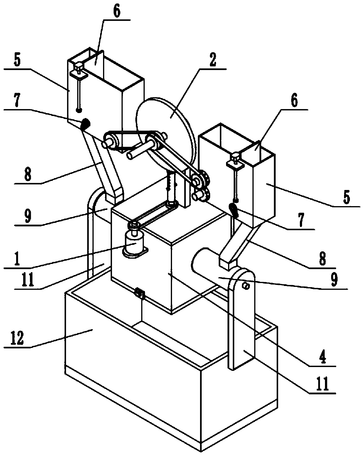
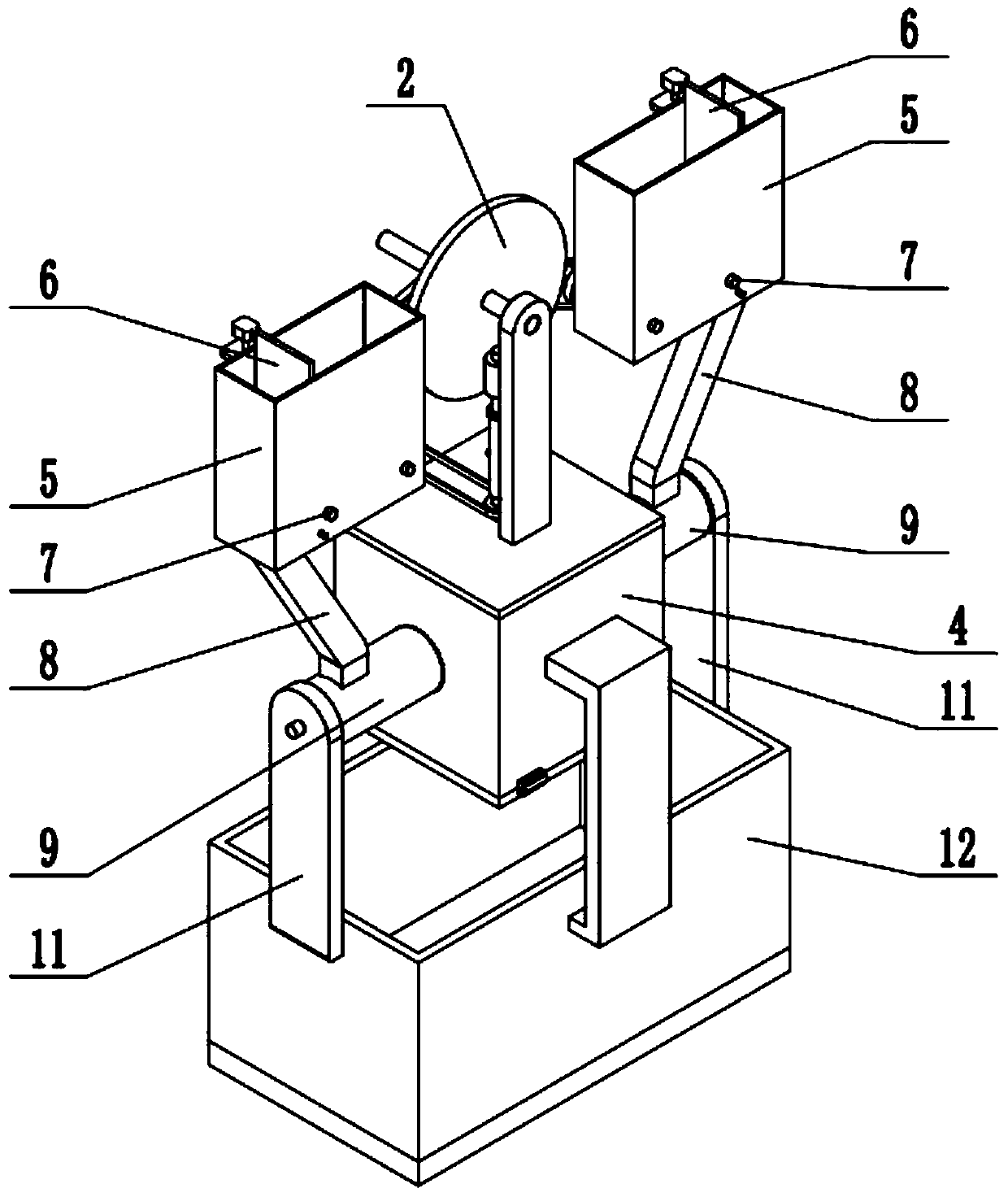
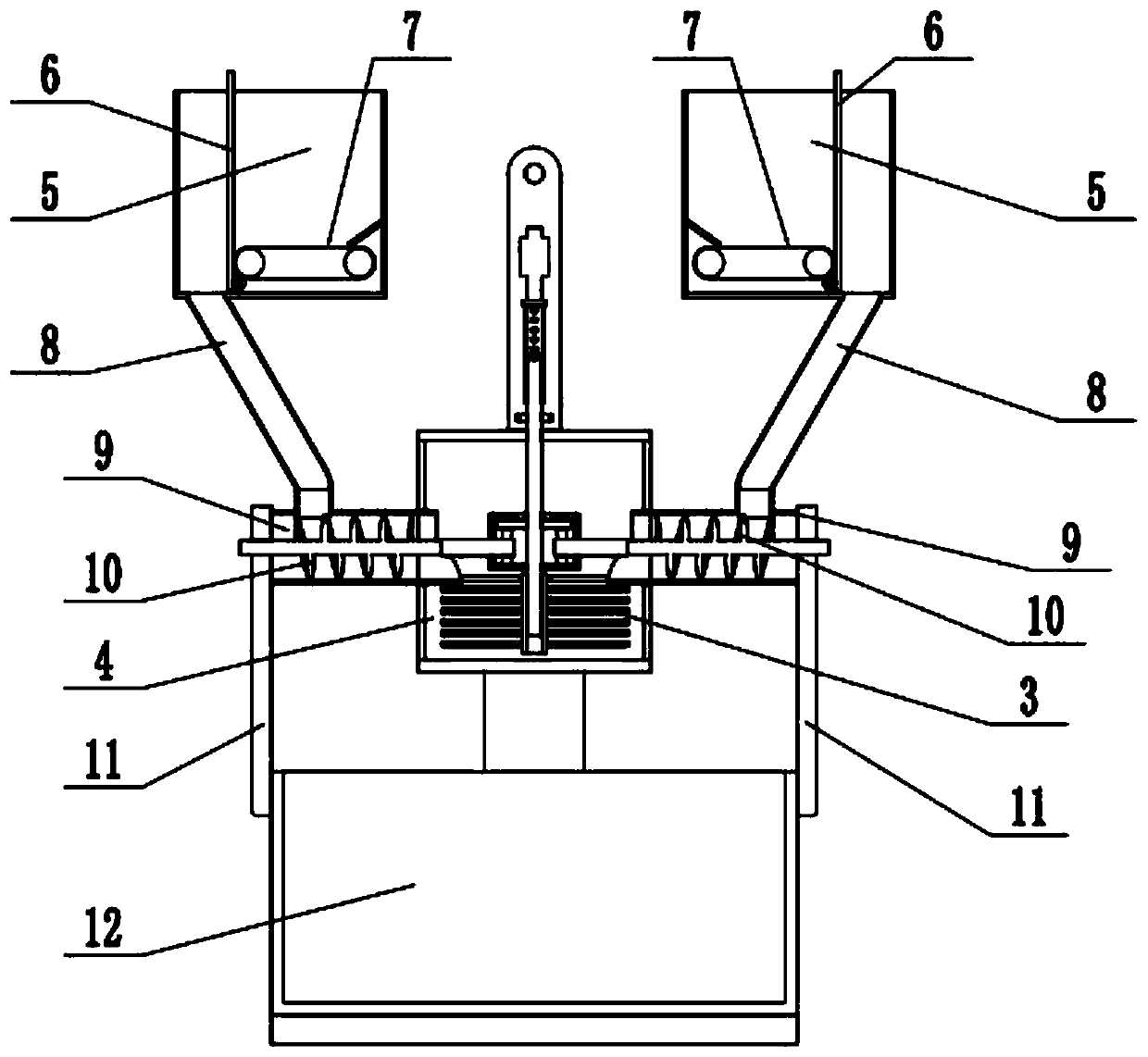
[0033] Such as Figure 1-12 As shown, a biomass fertilizer preparation system includes a servo motor 1, a variable speed transmission mechanism 2, a mixing mechanism 3, a mixing box 4, a storage box 5, a baffle plate 6, a conveyor belt 7, a drop pipe 8, a conveyor Feed pipe 9, feeding mechanism 10, side shelf plate 11 and fertilizer collection box 12, described material storage box 5 is provided with two, and the lower end of two material storage boxes 5 is respectively fixedly connected with a material drop pipe 8, two drop tubes The lower end of the feed pipe 8 is fixedly connected to the upper end of a feed pipe 9 respectively, and the inner ends of the two feed pipes 9 are respectively fixedly connected to the left and right ends of the mixing box 4; the outer ends of the two feed pipes 9 are respectively fixedly connected to the On one side frame plate 11, the lower ends of two side frame plates 11 are respectively fixedly connected to the left and right ends of the ferti...
specific Embodiment approach 2
[0034] Such as Figure 1-12 As shown, the variable speed transmission mechanism 2 includes a passive sprocket 2-1, a rotating shaft 2-2, a rotating tube 2-3, a positioning screw, a nut, an upper transmission shaft 2-4, a driving roller 2-5, and a friction transmission disc 2 -6, linkage shaft 2-7, axle frame plate 2-8, first pulley 2-9, second pulley 2-10, third pulley 2-11, fourth pulley 2-12, first pulley Short shaft 2-13, second short shaft 2-14, third short shaft 2-15, first gear 2-16, second gear 2-17, gearbox 2-18, driving bevel gear 2-19, passive The bevel gear 2-20 and the side transmission shaft 2-21, the driving sprocket 1-1 is connected to the passive sprocket 2-1 through a chain drive, and the passive sprocket 2-1 is fixedly connected to the middle end of the rotating shaft 2-2, and the rotating shaft The upper end of 2-2 is slidably connected in the rotating tube 2-3, and the rotating shaft 2-2 is provided with a positioning jack, and the rotating tube 2-3 is pro...
specific Embodiment approach 3
[0036] Such as Figure 1-12 As shown, the mixing mechanism 3 includes a rotating sleeve 3-1 and a stirring roller 3-2; the rotating sleeve 3-1 is fixedly connected to the bottom end of the rotating shaft 2-2; the rotating sleeve 3-1 A plurality of stirring rollers 3-2 are evenly arranged around the surface of the tube. When the rotating shaft 2-2 rotates, it can drive the rotating sleeve 3-1 to rotate around its own axis, and when the rotating sleeve 3-1 rotates, it can drive a plurality of stirring rollers 3-2 to rotate and mix the raw materials.
PUM
 Abstract
Description
Claims
Application Information
 - R&D
- Intellectual Property
- Life Sciences
- Materials
- Tech Scout
- Unparalleled Data Quality
- Higher Quality Content
- 60% Fewer Hallucinations
Browse by: Latest US Patents, China's latest patents, Technical Efficacy Thesaurus, Application Domain, Technology Topic, Popular Technical Reports.
© 2025 PatSnap. All rights reserved.Legal|Privacy policy|Modern Slavery Act Transparency Statement|Sitemap|About US| Contact US: help@patsnap.com


