Eureka AIR delivers breakthrough ideas for toughest innovation challenges, trusted by R&D personnel around the world.

Packaging structure of silicon photonic optical module and packaging method thereof

A packaging structure and silicon photonics technology, which is applied to the assembly of printed circuits with electrical components, printed circuits connected with non-printed electrical components, semiconductor devices, etc., can solve the problem of affecting signal integrity, unfavorable control of gold wire bonding length, Increase production and packaging costs and other issues to achieve the effect of enhancing the ability to resist electromagnetic interference, reducing the length of gold wire bonding, and ensuring integrity

Active Publication Date: 2019-06-04
JIANGSU HENGTONG PHOTOELECTRIC +1
View PDF8 Cites 5 Cited by
  • Summary
  • Abstract
  • Description
  • Claims
  • Application Information

AI Technical Summary

Problems solved by technology

[0006] The first is to use COB packaging, and its technical defects mainly have two points
The first point: the high-speed signal line connects the silicon photonics chip transmitting unit and receiving unit to the Driver chip and the TIA chip respectively through gold wire bonding, and connects the Driver chip and the TIA chip to the PCBA circuit board in the same way; In module circuits, especially at rates above 25Gbps, the shorter the gold wire bonding length, the better the integrity of high-frequency signal transmission; however, the length of gold wire bonding depends on the silicon photonic chip, IC chip, PCBA pad The distance between them, including the horizontal direction and the vertical direction; the COB packaging form cannot control the height difference of different chip pads in the vertical direction, which is unfavorable for the length control of gold wire bonding, which in turn causes the wire length to be too large and affects high frequency signal integrity
The second point: directly attaching the silicon photonic chip emission unit to the PCBA circuit board does not control the heat dissipation of the laser well, which leads to the temperature characteristic drift of the laser and modulator, and affects the quality of the optical signal generation of the silicon photonic module.
[0007] The second is to adopt the TROSA package form, and its technical defects mainly have two points
The first point: the same as the COB package, that is, the height difference of different chip pads in the vertical direction cannot be controlled, which is unfavorable for the control of the gold wire bonding length and affects signal integrity.
The second point: this type of packaging needs to connect the FPC pads to the PCBA pads by thermocompression welding, the process reliability is not good, resulting in low production yield; on the other hand, this type of packaging process is complex, increasing production and Package cost

Method used


Image

  • Packaging structure of silicon photonic optical module and packaging method thereof
  • Packaging structure of silicon photonic optical module and packaging method thereof
  • Packaging structure of silicon photonic optical module and packaging method thereof

Examples


Embodiment Construction

[0038] The present invention will be further described below in conjunction with the accompanying drawings and specific embodiments, so that those skilled in the art can better understand the present invention and implement it, but the examples given are not intended to limit the present invention.

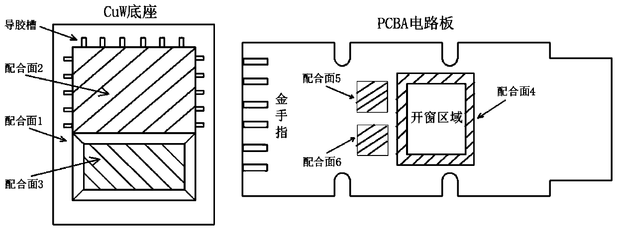
[0039] A packaging structure of a silicon photonic optical module, including: a PCBA circuit board, a CuW base, a CuW cover, a silicon photonic chip emitting unit and a silicon photonic chip receiving unit, a driver chip, a transimpedance amplifier chip, and a TEC;

[0040] The PCBA circuit board is provided with a window area; the edge of the lower surface of the window area is the fourth mating surface; the fifth mating surface and the sixth mating surface on the PCBA circuit board;

[0041] The edge of the upper surface of the CuW base is the first mating surface; the CuW base is also provided with a second mating surface and a third mating surface;

[0042] The first mating su...


PUM


Abstract

The invention discloses a packaging structure of a silicon photonic optical module and a packaging method thereof. The packaging structure of the silicon photonic optical module comprises a PCBA circuit board, a CuW base, a CuW cover, a silicon photonic chip emitting unit, a silicon photonic chip receiving unit, a driving chip, a transimpedance amplifier chip and a semiconductor refrigerator (TEC), wherein the PCBA circuit board has a windowing region; edges of the lower surface of the windowing region form a fourth mating surface; the upper surface of the PCBA circuit board has a fifth matingsurface and a sixth mating surface near the windowing region; edges of the upper surface of the CuW base form a first mating surface; the CuW base further has a second mating surface and a third mating surface; and the first mating surface and the fourth mating surface are adhered by means of a UV curing glue. The packaging structure has the beneficial effects of using the CuW structural member and a nozzle with a height control function to eliminate the height difference of patches between the silicon photonic chip and the IC chip, thereby reducing the bonding length of gold wires between different chip pads.

Description

technical field [0001] The invention relates to the field of semiconductor packaging, in particular to a packaging structure of a silicon photonic optical module and a packaging method thereof. Background technique [0002] Silicon photonics technology has been generally recognized by the optical communication industry as the core technology of next-generation optical communication devices and module systems, and it is one of the most promising solutions to solve the problems of data center interconnection rate limitation, cost, and power consumption. Silicon photonics technology is compatible with CMOS technology, and integrates a series of optical components such as light source, modulator, detector, multiplexer / demultiplexer, and waveguide on a single silicon substrate, which greatly reduces the raw material production cost of photonic chips and optical modules. packaging and testing costs. Silicon photonics technology can greatly improve the integration of devices and r...

Claims


Application Information

Patent Timeline
Patent Type & Authority Applications(China)
IPC IPC(8): H01L25/04H01L25/075H05K1/18H05K3/30H05K3/32H05K13/04
CPCH01L2224/48137
Inventor 朱宇陈奔沈笑寒梁巍
Owner JIANGSU HENGTONG PHOTOELECTRIC
Why Eureka
Eureka Blog
Learn More