Fuel cell with separation and transmission of materials and efficient utilization of fuel and operating method thereof

A fuel cell and fuel technology, applied in fuel cells, circuits, electrical components, etc., can solve the problems of gas and fuel mixing, difficulty in discharging, and uneven distribution of fuel concentration, so as to improve reaction efficiency, ensure high concentration, and avoid blending effect

Active Publication Date: 2019-06-07
XI AN JIAOTONG UNIV
View PDF6 Cites 0 Cited by
  • Summary
  • Abstract
  • Description
  • Claims
  • Application Information

AI Technical Summary

Problems solved by technology

In this process, with the flow of fuel in the flow channel and the diffusion reaction in the electrode, the fuel consumption products continue to enter the flow channel, and the concentration of the fuel gradually decreases, which leads to uneven distribution of the fuel concentration in the electrode and reduces the electrode quality. Reaction efficiency, further reducing the operating efficiency of direct liquid fuel cells
[0005] At the same time, borohydride solutions are prone to hydrolysis to generate hydrogen under natural conditions, and hydrogen peroxide is prone to produce oxygen under natural conditions. This problem reduces the conversion rate of fuel and oxidant chemical energy to electrical energy to a certain extent; at the same time, in traditional In the flow path, the generated gas and fuel are easily mixed, difficult to discharge, and easily trapped inside the battery, affecting the efficient operation of the battery
[0006] Therefore, in order to solve the problems of fuel product mixing, uneven fuel concentration distribution, and low cell reaction efficiency during the flow reaction process of fuel cell fuel, a fuel product phase separation transfers downstream, the fuel concentration is uniformly distributed, and the fuel oxidant is efficiently utilized. High-efficiency fuel cells are urgently needed

Method used


Image

  • Fuel cell with separation and transmission of materials and efficient utilization of fuel and operating method thereof
  • Fuel cell with separation and transmission of materials and efficient utilization of fuel and operating method thereof
  • Fuel cell with separation and transmission of materials and efficient utilization of fuel and operating method thereof

Examples


Embodiment Construction

[0043] The present invention will be described in further detail below in conjunction with the accompanying drawings and specific embodiments, but not as a limitation of the present invention.

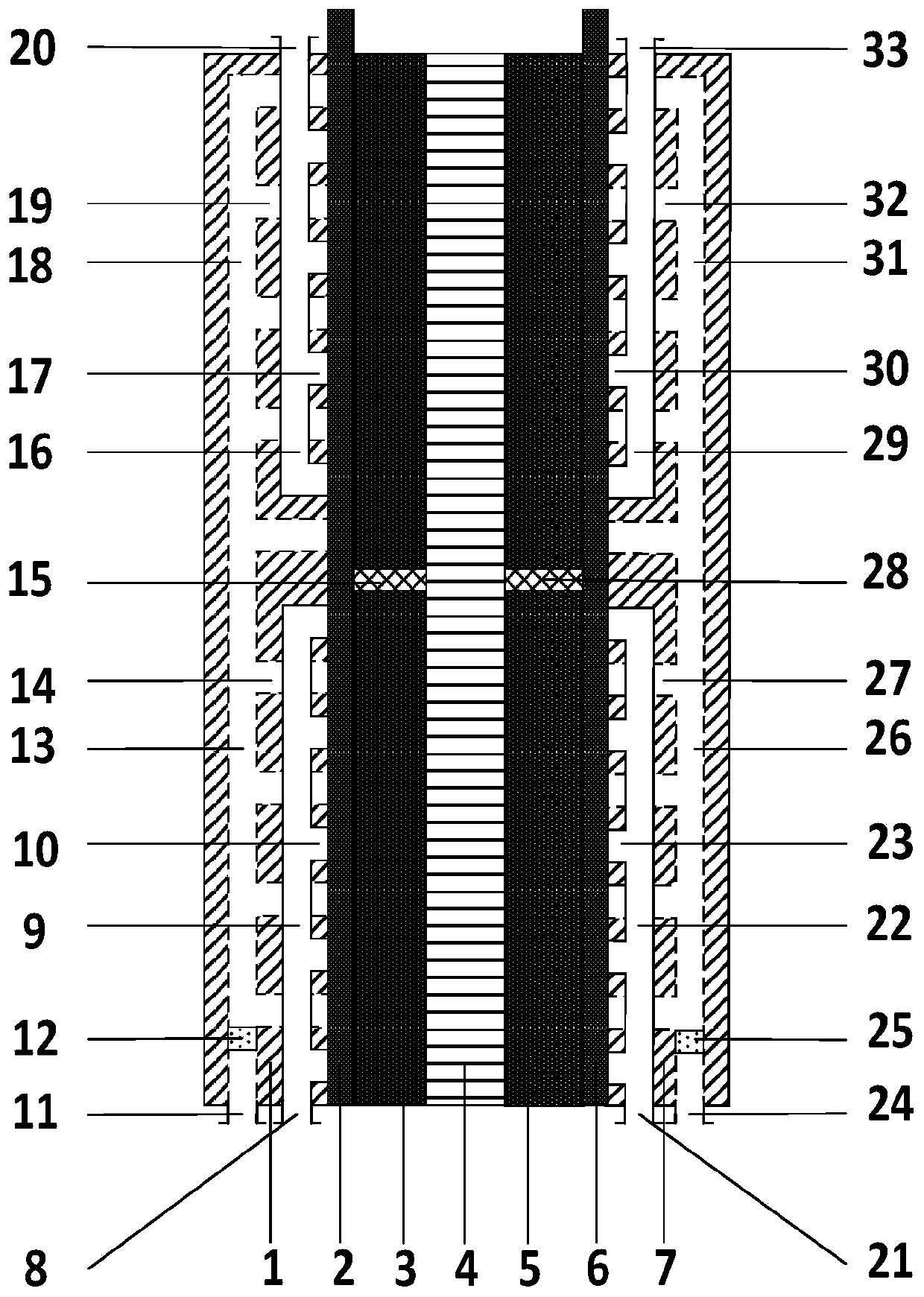
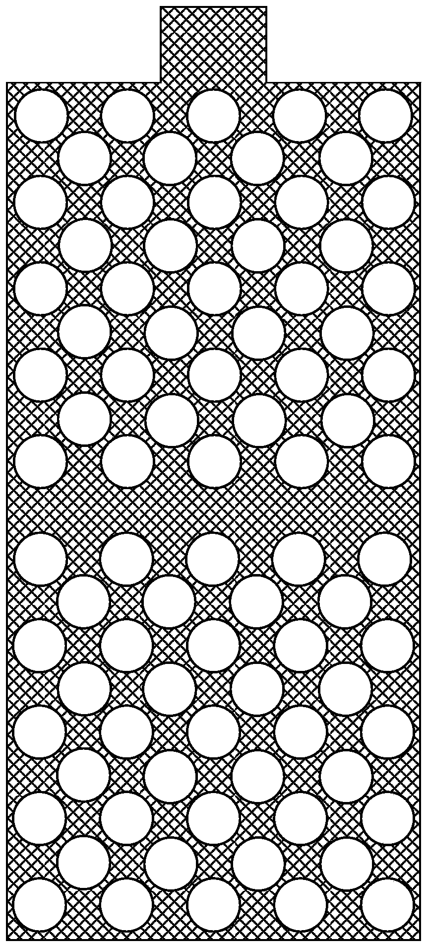
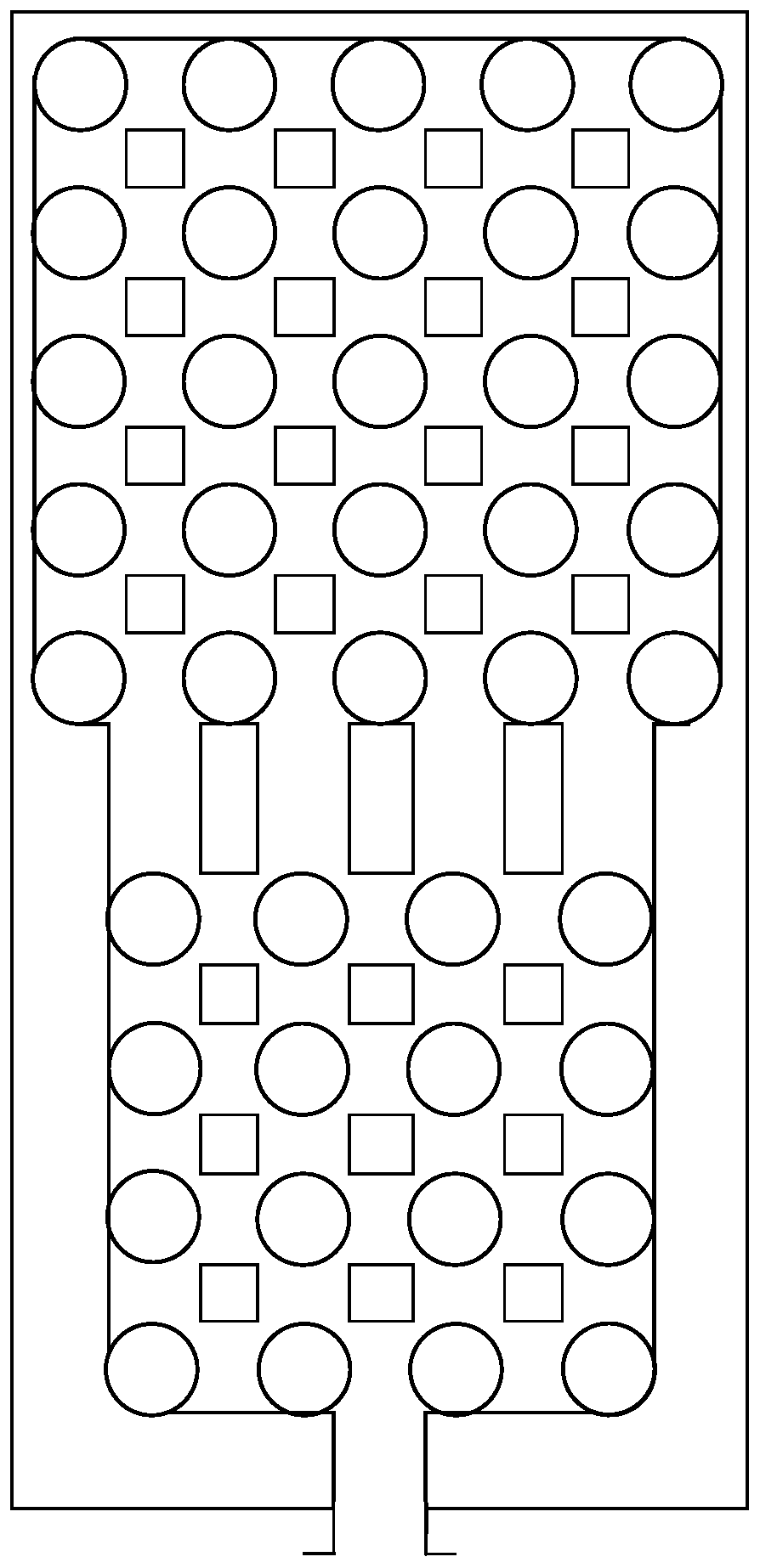
[0044] see Figure 1-2 , the material separation and transport fuel efficient utilization fuel cell of the present invention comprises an anode flow field plate 1, an anode buffer chamber 2, an anode electrode 3, an exchange membrane 4, a cathode electrode 5, a cathode buffer chamber 6 and a cathode arranged on the fuel cell body Flow field plate7.

[0045] The anode flow field plate 1 is independently provided with a borohydride supply pipeline 9, a borohydride product discharge pipeline 13, a hydrogen product discharge pipeline 16 and a hydrogen supply pipeline 18, and the anode flow field plate 1 is provided with There are borohydride inlet 8, borohydride product outlet 11 and hydrogen product outlet 20, one end of borohydride supply pipeline 9, borohydride product discharge pipeli...


PUM


Abstract

The present invention discloses a fuel cell with separation and transmission of materials and efficient utilization of fuel and an operating method thereof. The fuel cell is provided with an anode flow filed plate and a cathode flow field plate which are both internally independently provided with raw material supply pipelines and branches, and product discharge pipelines and branches, and are both internally independently provided with hydrogen product discharge pipelines, hydrogen supply pipelines and branches, oxygen product discharge pipelines, and oxygen supply branches. The raw materialsand the products are separately transmitted, and the hydrogen and oxygen products are introduced in an electrode for secondary utilization so as to ensure the high concentration of the electrode cathode fuel oxide, improve the reaction efficiency, improve the fuel oxidizing agent utilization and develop the discharge efficiency of the battery to the maximum extent.

Description

technical field [0001] The invention relates to the technical field of fuel cells, in particular to a fuel cell for high-efficiency utilization of fuel for separation and transmission of materials and a working method thereof. Background technique [0002] Fuel cell technology is a new type of power generation technology, which can directly convert the chemical energy existing in fuel and oxidant into electrical energy, with high efficiency, no pollution, no noise, high reliability, modularization, and quick response to load changes And other significant advantages, it is considered to be the ultimate solution to the energy crisis. Fuel cells are mainly composed of ion exchange membranes, cathode and anode electrodes and bipolar plates. Wherein the membrane electrode (membrane electrode assembly, MEA) composed of the cathode electrode, the ion exchange membrane and the anode electrode is the place where the electrochemical reaction of the fuel cell occurs. Fuel and oxidant...

Claims


Application Information

Patent Timeline
IPC IPC(8): H01M8/0258H01M8/04089
CPCY02E60/50
Inventor 李印实王睿何雅玲
Owner XI AN JIAOTONG UNIV
Why Eureka
Try Eureka