Electrostatic spinning method for melt
A melt electrospinning, electrospinning technology, applied in textile and papermaking, filament/thread forming, fiber processing and other directions, to achieve the effect of wide application, guaranteed processability and simple process flow
- Summary
- Abstract
- Description
- Claims
- Application Information
AI Technical Summary
Problems solved by technology
Method used
Image
Examples
Embodiment 1
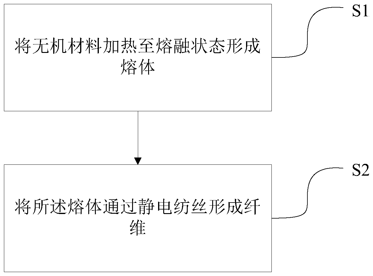
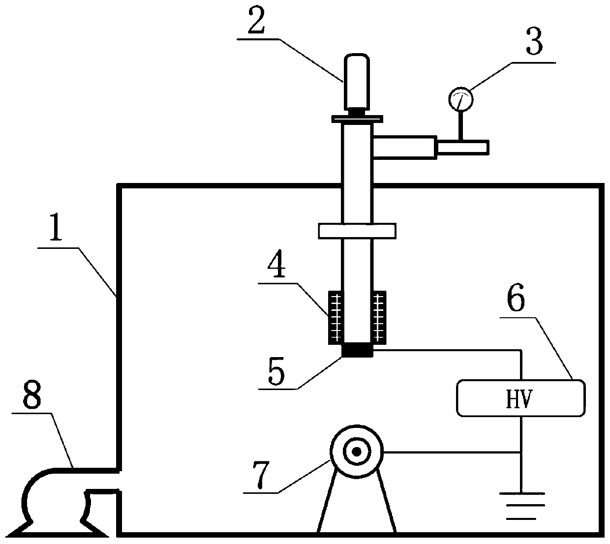
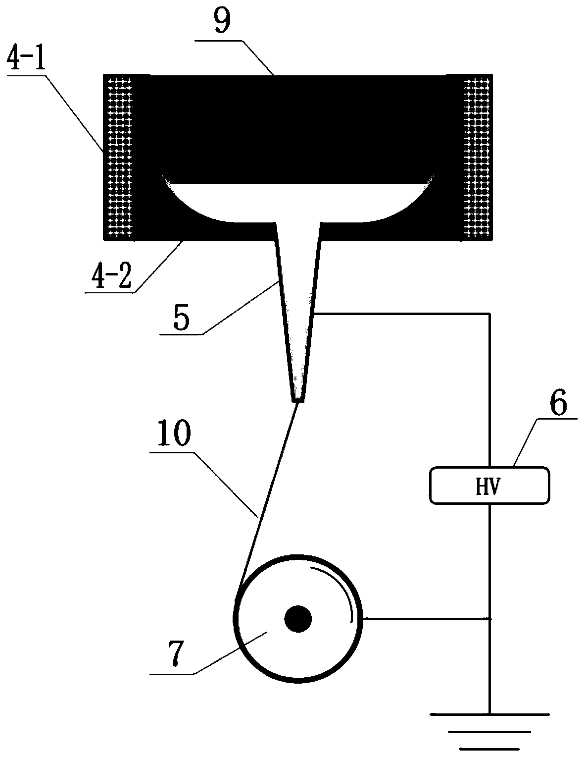
[0046] Close all valves of the device, turn on the vacuum pump, and evacuate the pressure in the cavity to below 4Pa; close the valve of the vacuum pump, open the nitrogen valve, and return the pressure in the cavity to normal pressure; repeat the vacuum pumping and nitrogen replacement twice. Maintain the nitrogen atmosphere and normal pressure in the cavity, add 10g of silicon powder into the crucible through the feeding system, heat it to about 1420°C to melt the silicon powder, adjust the pressure of the crucible so that the melt is extruded at a flow rate of 1 μL / min, and the spinneret The distance from the collector is 150mm, and the spinning is carried out at a voltage of 10kV. It is visible to the naked eye that the fibrous substance extends from the nozzle to the collector. After collecting for 1 hour, the samples were taken out and characterized by microscope, the results showed that the diameter of silicon nanofibers was 1000-1500nm.
Embodiment 2
[0048] Close all valves of the device, turn on the vacuum pump, and evacuate the pressure in the cavity to below 4Pa; close the valve of the vacuum pump, open the nitrogen valve, and return the pressure in the cavity to normal pressure; repeat the vacuum pumping and nitrogen replacement twice. Maintain the nitrogen atmosphere and normal pressure in the cavity, add 10g of silicon powder into the crucible through the feeding system, heat it to about 1420°C to melt the silicon powder, adjust the pressure of the crucible so that the melt is extruded at a flow rate of 2μL / min, and the spinneret The distance from the collector is 150mm, and the spinning is carried out at a voltage of 12kV. It is visible to the naked eye that the fibrous substance extends from the nozzle to the collector. After 1 hour of collection, the samples were taken out and characterized by microscopy, the results showed that the diameter of silicon nanofibers was 500-800nm.
Embodiment 3
[0050] Close all valves of the device, turn on the vacuum pump, and evacuate the pressure in the cavity to below 4Pa; close the valve of the vacuum pump, open the nitrogen valve, and return the pressure in the cavity to normal pressure; repeat the vacuum pumping and nitrogen replacement twice. Maintain the nitrogen atmosphere and normal pressure in the cavity, add 10g of silicon powder into the crucible through the feeding system, heat it to about 1420°C to melt the silicon powder, adjust the pressure of the crucible so that the melt is extruded at a flow rate of 5 μL / min, and the spinneret The distance from the collector is 150mm, and the spinning is carried out at a voltage of 20kV. It is visible to the naked eye that the fibrous substance extends from the nozzle to the collector. After 1 hour of collection, the samples were taken out and characterized by microscopy, the results showed that the diameter of silicon nanofibers was 200-400nm.
PUM
| Property | Measurement | Unit |
|---|---|---|
| melting point | aaaaa | aaaaa |
| particle diameter | aaaaa | aaaaa |
| diameter | aaaaa | aaaaa |
Abstract
Description
Claims
Application Information
 - R&D
- Intellectual Property
- Life Sciences
- Materials
- Tech Scout
- Unparalleled Data Quality
- Higher Quality Content
- 60% Fewer Hallucinations
Browse by: Latest US Patents, China's latest patents, Technical Efficacy Thesaurus, Application Domain, Technology Topic, Popular Technical Reports.
© 2025 PatSnap. All rights reserved.Legal|Privacy policy|Modern Slavery Act Transparency Statement|Sitemap|About US| Contact US: help@patsnap.com


