Loss compensation type electrically tuned active resonator and loss compensation method thereof

A source resonator and loss compensation technology, applied in resonators, waveguide devices, circuits, etc., can solve the problems of invariable Q value, low Q value, and inability to be electrically tuned, and achieve controllable insertion loss and rectangular characteristics Good, volume reduction effect

Pending Publication Date: 2019-06-14
曾运华
View PDF0 Cites 1 Cited by
  • Summary
  • Abstract
  • Description
  • Claims
  • Application Information

AI Technical Summary

Problems solved by technology

[0003] The purpose of the present invention is to overcome and solve the shortcomings and technical problems of existing microwave resonators such as large loss, large volume, inconvenient integration, inability to be electrically tuned, narrow tuning range, low Q value, and invariable Q value, and provide a microwave resonator with small loss , small size, can be integrated on the chip, can be tuned by low-voltage DC voltage, wide tuning range, high Q value, and variable Q value microwave resonator, that is, a loss compensation type electronically adjustable active resonator (hereinafter referred to as "active resonator") consisting of an input port, a parallel resonant body, a compensation amplifier, a signal switch, and a variable capacitor; said compensation amplifier is a single-stage or multi-stage amplifier whose final stage is An emitter follower or a source follower, that is, a common-collector amplifying circuit or a common-drain amplifying circuit; the parallel resonator is a conductor with one end open, the other end grounded, and any shape on the circuit; the open-circuit end is The upper and ground terminals are lower, and the upper and lower taps are used to divide the parallel resonant body into three sections, which are the first section, the second section, and the third section from top to bottom; The open circuit terminal is electrically connected, the output terminal of the compensation amplifier is electrically connected to the lower tap end of the parallel resonant body; the signal switch is connected in parallel with the second section of the parallel resonant body, that is, it is electrically connected between the upper and lower taps of the parallel resonant body The variable capacitor is connected in parallel with the parallel resonant body; the input port is electrically connected to the open end of the parallel resonant body

Method used


Image

  • Loss compensation type electrically tuned active resonator and loss compensation method thereof
  • Loss compensation type electrically tuned active resonator and loss compensation method thereof
  • Loss compensation type electrically tuned active resonator and loss compensation method thereof

Examples


Embodiment 1

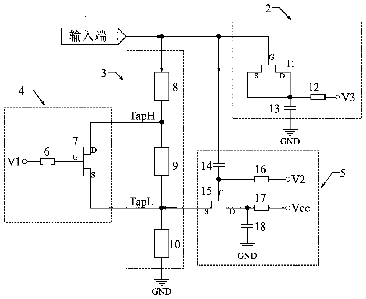
[0022] Embodiment one: if figure 2 As shown, the parallel resonator 3 is formed by connecting the microstrip lines 8, 9, and 10 end to end, the other end of the microstrip line 10 is grounded, the other end of the microstrip line 8 is the open circuit end of the parallel resonator 3, and the upper tap TapH At the interconnection of the microstrip lines 8 and 9, the lower tap TapL is at the interconnection of the microstrip lines 9 and 10, the first section of the parallel resonator 3 contains the microstrip line 8, and the second section contains the microstrip line 9, The third section includes a microstrip line 10; the compensation amplifier 5 is composed of a field effect transistor 15, a DC blocking capacitor 14, a high frequency blocking resistor 16, a current limiting resistor 17, and a high frequency bypass capacitor 18. The gate of the field effect transistor 15 is connected to the The DC blocking capacitor 14 is electrically connected to the high frequency blocking r...

Embodiment 2

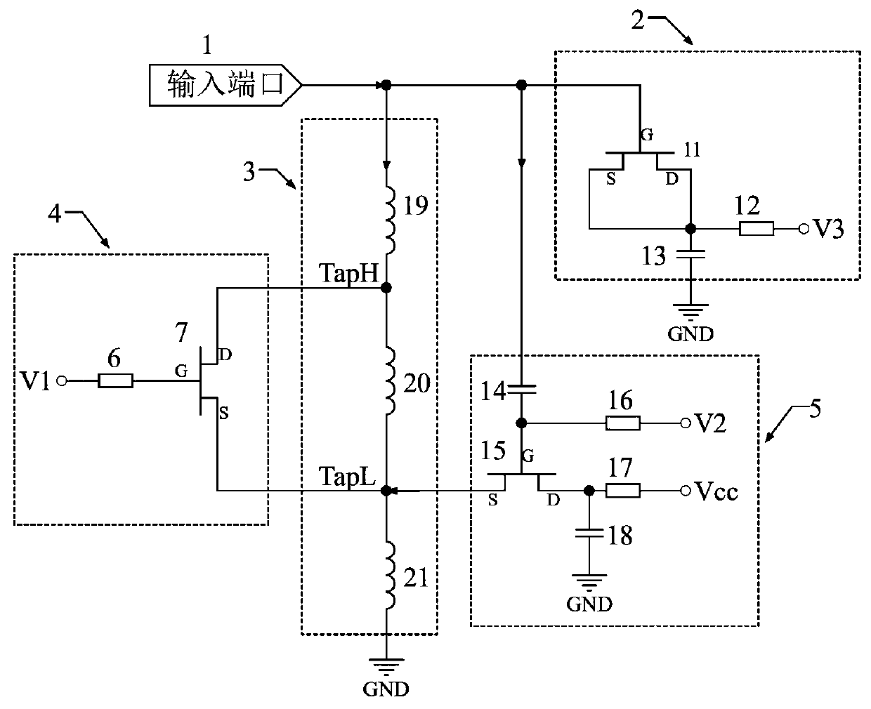
[0025] Embodiment two: if image 3 As shown, the difference from Embodiment 1 is that the microstrip lines 8, 9, and 10 are replaced by inductors 19, 20, and 21 respectively, that is, the parallel resonant body 3 is formed by connecting the inductors 19, 20, and 21 end to end. , the other end of the inductor 21 is grounded, the other end of the inductor 19 is the open end of the parallel resonator 3, the upper tap TapH is at the interconnection of the inductors 19 and 20, and the lower tap TapL is at the interconnection of the microstrip lines 20 and 21, The first segment of the parallel resonator 3 includes an inductor 19, the second segment includes an inductor 20, and the third segment includes an inductor 21; the other parts of the active resonator and their connections and functions are exactly the same as those in the first embodiment.

[0026] As a preferred solution, Embodiment 2 is the same as Embodiment 1. A loss-compensated electronically tuned active resonator is s...


PUM


Abstract

The invention discloses a loss compensation type electrically tuned active resonator and a loss compensation method thereof. The loss compensation type electrically tuned active resonator comprises aninput port (1), a parallel resonance body (3), a compensation amplifier (5), a signal switch (4) and a variable capacitor (2); the parallel resonance body (3) and the variable capacitor (2) form a parallel LC (inductance capacitance) resonator; the compensation amplifier (5) amplifies a microwave signal from the open circuit end of the parallel resonance body (3) to form a compensation current, and then the compensation current is injected into the parallel resonance body (3) from other parts of the parallel resonance body (3), so that a signal current on the parallel resonance body (3) is enhanced and the loss in the resonator is compensated; the compensation amount of the loss of the active resonator can be changed by changing the current gain of the compensation amplifier (5), so thatthe Q value of the active resonator is adjustable; and the signal switch (4) is combined with the variable capacitor (2), so that the active resonator can be continuously tunable in a frequency band division mode. The loss compensation type electrically tuned active resonator can be realized by using an integrated circuit process of gallium arsenide, silicon and the like, and low-voltage direct-current voltage tuning is adopted; and the size is small, the resonant frequency is adjustable, the Q value (quality factor) is adjustable, and the tuning range is wide.

Description

technical field [0001] The invention relates to the field of microwave resonators, in particular to a microwave active resonator composed of parallel resonators, compensation amplifiers, variable capacitors, signal switches and other components and components and a method for compensating the loss of the resonators. Background technique [0002] Microwave resonators are important components of electronic devices such as microwave filters, microwave combiners, microwave multiplexers, microwave oscillators, microwave voltage-controlled oscillators, and microwave amplifiers. There are many kinds of existing microwave resonators, such as microstrip resonators, spiral resonators, ceramic resonators, waveguide resonators, coaxial cavity resonators, dielectric resonators, etc. Most of them have large loss, large volume, and inconvenient integration. , Can not be tuned or can only be tuned mechanically, can not be tuned electrically, the tuning range is narrow, the Q value (quality ...

Claims


Application Information

Patent Timeline
IPC IPC(8): H01P7/00H01P7/08
Inventor 曾运华
Owner 曾运华
Why Eureka
Try Eureka