Buck terminal coupled inductor buck-boost conversion circuit and control method thereof
A buck-boost conversion, coupled inductance technology, applied in the direction of adjusting electrical variables, control/regulating systems, converting DC power input to DC power output, etc., can solve problems such as unfavorable efficiency and reduction, and achieve a simple and high-efficiency control scheme. , easy to achieve effect
- Summary
- Abstract
- Description
- Claims
- Application Information
AI Technical Summary
Problems solved by technology
Method used
Image

Examples
Embodiment 1
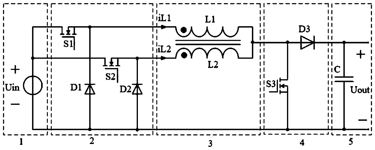
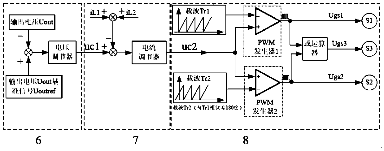
[0033] refer to Figure 1-2, a buck-side coupled inductance-type buck-boost conversion circuit and control method, which includes an input DC voltage source 1, a step-down circuit 2, a coupling inductor 3, a boost circuit 4, an output filter capacitor 5, and a voltage loop controller 6 , current loop controller 7 and PWM generator 8, it is characterized in that: input DC voltage source 1 comprises input DC voltage source Uin, the positive pole of input DC voltage source Uin is connected with the drain electrode of first power switch tube S1 and the second power respectively The drains of the switching tube S2 are connected; the step-down circuit 2 includes the first power switching tube S1, the first freewheeling diode D1, the second power switching tube S2, the second freewheeling diode D2, and the source of the first power switching tube S1 The pole is connected to the cathode of the first freewheeling diode D1, and the junction of the two is connected to the end of the same...
Embodiment 2
[0035] refer to image 3 -4, Since the coupling coefficient of the coupled inductor is not less than 0.9, the mutual inductance LM of the coupled inductor is much larger than the two leakage inductances (L1-LM, L2-LM) in the coupled inductor, so the two leakage inductances (L1-LM, During the commutation process of L2-LM) current (iL1, iL2), the current in the mutual inductance LM of the coupled inductor can be regarded as a constant current source; and the inductance L1 of the coupled inductor is assumed to be L2. Therefore, the working principle of the buck-side coupled inductive buck-boost conversion circuit and control method described in Embodiment 1 is briefly described as follows:
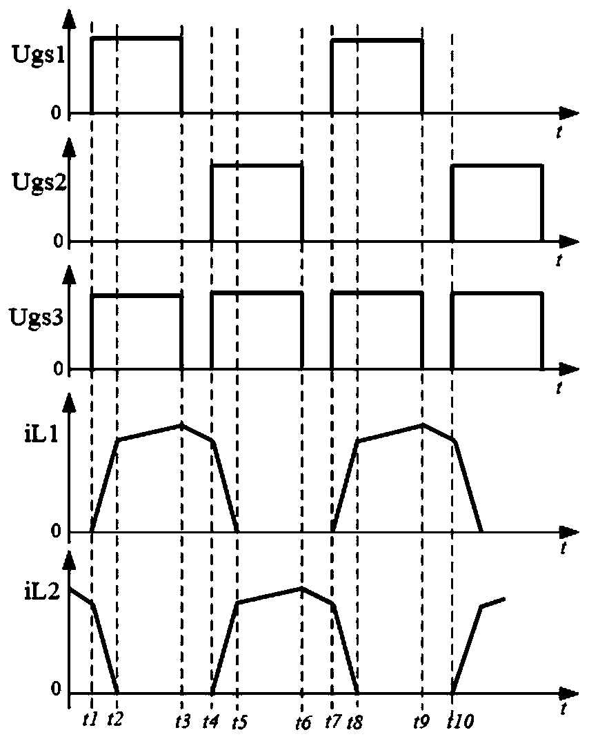
[0036] 1. Working mode (1) (t1-t2 time period)
[0037] Such as image 3 And shown in Figure 4(a). At time t1, the first power switch S1 and the third power switch S3 are turned on. Under the action of the input DC voltage source voltage Uin, the current iL1 on the leakage inductance L1-LM...
Embodiment 3
[0049] refer to Figure 5-7 . The main simulation experiments are done with a buck-side coupled inductive buck-boost conversion circuit and control method described in embodiment 1 and embodiment 2.
[0050] The simulation parameters are as follows: the input DC voltage source voltage Uin is 20V-60V, the output voltage Uout is controlled at 28.5V, the switching frequency of the first power switch S1 and the second power switch S2 is 50kHz, and the third power switch S3 is 100kHz , the inductors L1 and L2 in the coupled inductor are 24μH, the coupling coefficient is 0.9, the output filter capacitor C is 940μF, and the load R is a 5.6Ω resistive load.
[0051] Figure 5 The simulation waveforms of the input DC source voltage Uin and the output voltage Uout when the input DC source voltage Uin varies between 20V and 60V are given. It can be seen that when the input DC source voltage Uin changes, the output voltage Uout can be stabilized at 28.5V. When the input DC source volt...
PUM
 Abstract
Description
Claims
Application Information
 - Generate Ideas
- Intellectual Property
- Life Sciences
- Materials
- Tech Scout
- Unparalleled Data Quality
- Higher Quality Content
- 60% Fewer Hallucinations
Browse by: Latest US Patents, China's latest patents, Technical Efficacy Thesaurus, Application Domain, Technology Topic, Popular Technical Reports.
© 2025 PatSnap. All rights reserved.Legal|Privacy policy|Modern Slavery Act Transparency Statement|Sitemap|About US| Contact US: help@patsnap.com