Fuel cell separator
A fuel cell and separator technology, which is applied in the direction of fuel cells, fuel cell parts, power system fuel cells, etc., can solve the problem of increased contact resistance between the separator and the power generation unit, easy oxidation, titanium substrate and conductive carbon film Resisting problems such as weak adhesion, and achieving the effect of suppressing the increase in contact resistance and improving corrosion resistance
Pending Publication Date: 2019-07-02
TOYOTA JIDOSHA KK
10 Cites 0 Cited by
AI-Extracted Technical Summary
Problems solved by technology
[0006] However, in the separators obtained by the production methods disclosed in Patent Documents 1 and 2, there may be regions where the adhesion force between the titanium substrate and the conductive carbon film is weak.
In the weak adhesion area, the...
Abstract
A method for manufacturing a fuel cell separator that ensures an improved corrosion resistance under usage environment of a fuel cell and restraining an increase of a contact resistance with a power generation unit by enhancing a sticking force of a conductive carbon film formed on a surface in contact with the power generation unit on a surface of a titanium substrate is provided. It is a methodfor manufacturing a fuel cell separator. The fuel cell separator 3 includes a contact portion 31 that is in contact with a power generation unit 2 so as to partition the power generation units 2 including electrodes 6 of the fuel cell 10, and includes a conductive carbon film 3e formed on the contact portion 31. First, a titanium substrate 3A that has a plurality of projecting portions 31A formedcorresponding to a shape of the contact portion 31 and recessed portions 21A for gas flow channels formed between the projecting portions 31A are prepared as a substrate of the separator 3. Next, a heat treatment is performed on the titanium substrate 3A in a state where a carbon sheet 9 is brought in contact with the projecting portions 31A such that carbon of the carbon sheet 9 diffuses in the projecting portions 31A.
Application Domain
Final product manufactureSolid state diffusion coating +2
Technology Topic
ChemistryCarbon film +6
Image
Examples
- Experimental program(1)
Example Embodiment
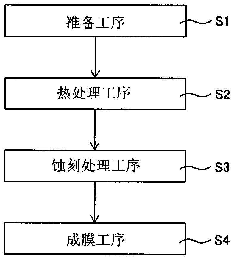
[0033] Hereinafter, the structure of this invention is demonstrated in detail based on an example of embodiment shown in drawing. Hereinafter, as an example, a case where the present invention is applied to a fuel cell mounted on a fuel cell vehicle or a fuel cell system including the same will be described, but the scope of application is not limited to such an example.
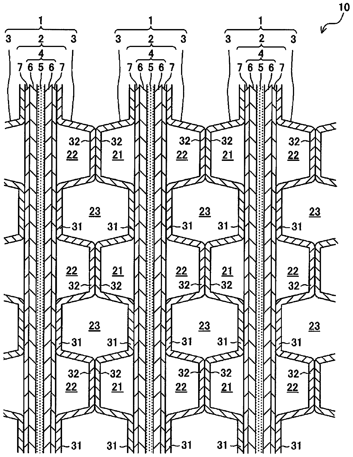
[0034] 1. Fuel cell 10 including separator 3
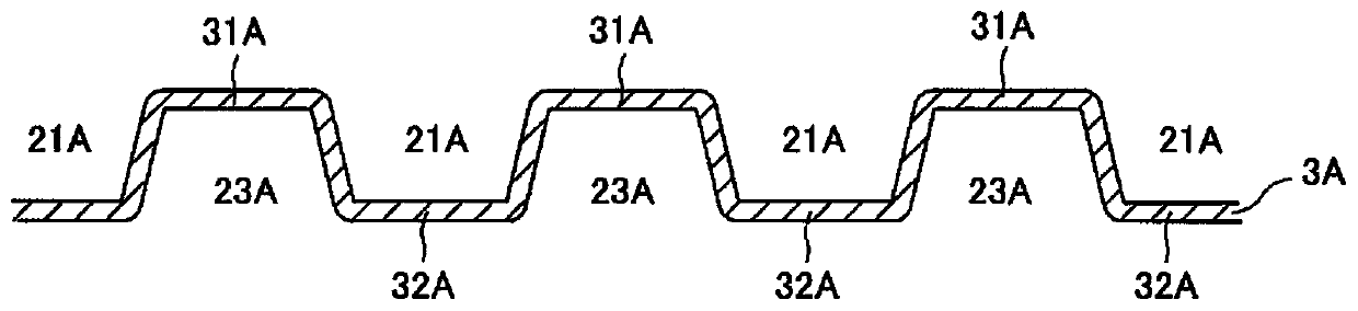
[0035] figure 1 It is a schematic cross-sectional view of a main part of a fuel cell 10 including a separator 3 according to an embodiment of the present invention. like figure 1 As shown, a fuel cell (fuel cell stack) 10 is stacked with a plurality of cells (single cells) 1 as basic units. Each cell 1 is a solid polymer fuel cell that generates an electromotive force through an electrochemical reaction between an oxidant gas (for example, air) and a fuel gas (for example, hydrogen gas). The battery 1 includes: a MEGA (Membrane Electrode & Gas Diffusion Layer Assembly) 2 ; and a separator (separator for a fuel cell) 3 in contact with the MEGA 2 so as to divide the MEGAs (power generation units) 2 . In addition, in the present embodiment, MEGA 2 is sandwiched between a pair of partition plates 3 , 3 .
[0036] MEGA 2 is formed by integrating a membrane electrode assembly (MEA: Membrane Electrode Assembly) 4 and gas diffusion layers 7 and 7 disposed on both surfaces. The membrane electrode assembly 4 is composed of an electrolyte membrane 5 and a pair of electrodes 6 , 6 bonded to sandwich the electrolyte membrane 5 . The electrolyte membrane 5 is formed of a proton-conductive ion-exchange membrane formed of a solid polymer material, and the electrodes 6 are formed of, for example, a porous carbon material carrying a catalyst such as platinum. The electrode 6 arranged on one side of the electrolyte membrane 5 serves as an anode, and the electrode 6 on the other side serves as a cathode. The gas diffusion layer 7 is formed of a gas-permeable conductive member such as a carbon porous body such as carbon paper or carbon cloth, or a metal porous body such as a metal mesh or metal foam.
[0037] In the present embodiment, MEGA2 is the power generation part of the fuel cell 10, and the separator 3 is in contact with the gas diffusion layer 7 of the MEGA2. In addition, when the gas diffusion layer 7 is omitted, the membrane electrode assembly 4 is a power generation part, and at this time, the separator 3 is in contact with the membrane electrode assembly 4 . Therefore, the power generation part of the fuel cell 10 includes the membrane electrode assembly 4 and is in contact with the separator 3 . The separator 3 is a plate-shaped member made of a metal having excellent conductivity, gas impermeability, etc., as a base material. The contact portion 31 on one side is in contact with the gas diffusion layer 7 of MEGA 2, and the contact portion 32 on the other side is in contact with the gas diffusion layer 7 of the MEGA 2. The other surface side of another adjacent separator 3 abuts against it. The contact portions 31 and 32 are power collectors that collect electric power generated by MEGA 2 as a power generator.
[0038]In this embodiment, each separator 3 is formed in a corrugated shape. Regarding the shape of the separator 3, the shape of the wave is an isosceles trapezoid, and the top of the wave is flat, and both ends of the top are angular with equal angles. In other words, each separator 3 has substantially the same shape when viewed from the front side and when viewed from the back side, and the tops (convex portions) serve as contact portions 31 and 32 of the separators 3 . Specifically, one gas diffusion layer 7 surface of MEGA 2 is in contact with a contact portion 31 that is the top of the separator 3 , and the other gas diffusion layer 7 surface of MEGA 2 is in contact with a contact portion 32 that is the top of the separator 3 . .
[0039] The gas flow path 21 defined between the gas diffusion layer 7 on the side of one electrode (i.e., the anode) 6 and the separator 3 is a flow path through which the fuel gas flows, and the gas flow path 21 on the side of the other electrode (i.e., the cathode) 6 The gas channel 22 defined between the gas diffusion layer 7 and the separator 3 is a channel through which the oxidizing gas flows. When the fuel gas is supplied to one of the opposing gas channels 21 across the battery 1 and the oxidizing gas is supplied to the other gas channel 22 , an electrochemical reaction occurs in the battery 1 to generate an electromotive force.
[0040] In addition, a certain battery 1 and another battery 1 adjacent thereto are arranged such that the electrode 6 serving as the anode and the electrode 6 serving as the cathode face each other. In addition, the contact portion 32 on the back side of the separator 3 arranged along the electrode 6 serving as the anode of one battery 1 and the contact portion 32 on the back side of the separator 3 arranged along the electrode 6 serving as the cathode of the other battery 1 Part 32 is in contact. Water serving as a refrigerant for cooling the batteries 1 flows through a space 23 defined between the separators 3 , 3 that are in surface contact between two adjacent batteries 1 .
[0041] 2. Manufacturing method of the separator 3
[0042] Below, refer to Figure 2 to Figure 8 , the method of manufacturing the separator 3 of the present embodiment will be described. figure 2 is used for figure 1 A flow chart illustrating a method of manufacturing the separator 3 for a fuel cell is shown. In addition, in the following, the method of manufacturing the separator 3 having the gas flow passage 21 for the fuel gas will be described, and the method of manufacturing the separator 3 having the gas flow passage 22 for the oxidizing gas is also the same, so details thereof will be omitted. illustrate.
[0043] 2-1. Preparatory process S1
[0044] image 3 Yes figure 2 It is a schematic cross-sectional view of the titanium base material 3A used as the base material of the separator 3 in the preparation process shown. Figure 4 Yes image 3 An enlarged cross-sectional view of the convex portion 31A is shown. like figure 2 As shown, in this embodiment, first, the preparatory step S1 is performed.
[0045] In the preparation step S1, a titanium base material 3A is prepared as a base material of the separator 3, and the titanium base material 3A has: a plurality of convex portions 31A, 31A, . . . formed corresponding to the shape of the contact portion 31; 31A, recessed portion 21A for the gas flow path between 31A. In addition, a convex portion 32A corresponding to the shape of the contact portion 32 is formed on the opposite side to the surface on which the convex portion 31A is formed, and a concave portion 23A for cooling water is formed therebetween. In this embodiment, the following sheet-shaped titanium base material is prepared, and the titanium base material is molded into a titanium base material 3A by pressing the titanium base material. The details are described below.
[0046] In this step, first, a sheet-shaped titanium base material made of a cold-rolled material is prepared. The titanium substrate is made of titanium or a titanium alloy. Examples of titanium include 1 to 4 types defined in JIS H 4600. Moreover, as a titanium alloy, Ti-Al, Ti-Nb, Ti-Ta, Ti-6Al-4V, Ti-Pd are mentioned, for example. However, it is not limited to the above-mentioned illustrations in any case.
[0047] By forming a base material made of titanium or a titanium alloy, it is possible to form a member that is light and has excellent corrosion resistance. The thickness of the titanium substrate is preferably a cold-rolled sheet material with a thickness of 0.05 to 1 mm. If the thickness is within this range, the requirements for weight reduction and thinning of the separator are satisfied, the strength and handleability as the separator are provided, and it is relatively easy to press into the shape of the separator.
[0048] A plurality of protrusions 31A, 31A... formed corresponding to the shape of the contact portion 31, and a plurality of protrusions 31A, 31A formed between the protrusions 31A, 31A are molded from the sheet-shaped titanium base material by press processing. The concave portion 21A for the gas flow path between them. Before forming the titanium carbide layer 3d in the heat treatment step S2 described later, the titanium base material 3A is formed by press working, so that the above-mentioned convex portion 31A, concave portion 21A, etc. can be easily formed from the highly formable titanium base material.
[0049] Here, if Figure 4 As shown, titanium oxide (specifically TiO 2 ) Passivation film 3b. The passivation film 3 b is an oxide film composed of titanium dioxide which is naturally oxidized from titanium in the air (in an atmosphere containing oxygen). Further, titanium carbide 3c is partially formed between the passivation film 3b of titanium oxide and the base material 3a. The titanium carbide 3c is formed by the carbon of the hydrocarbons contained in the rolling oil when rolling the sheet-shaped titanium base material 3A, which diffuses into the titanium during annealing after rolling.
[0050] 2-2. Heat treatment step S2
[0051] Next, heat treatment step S2 is performed. Figure 5 is used for figure 2 A diagram illustrating the heat treatment step S2 is shown. Image 6 Yes Figure 5 An enlarged cross-sectional view of the convex portion after the heat treatment step S2 shown. In the heat treatment step S2, in the state where the carbon sheet 9 is brought into contact with the convex portion 31A corresponding to the contact portion 31 in contact with at least the power generation unit 2 in the titanium base material 3A, the carbon of the carbon sheet 9 is directed toward the convex portion 31A. The titanium substrate 3A is heat-treated by diffusion. In addition, in the present embodiment, the same process is simultaneously performed in a state where the carbon sheet 9 is brought into contact with the convex portion 32A formed on the opposite side.
[0052] The carbon sheet 9 is not particularly limited as long as it is a flexible sheet whose surface contains carbon, and as long as a titanium carbide layer can be formed. Examples of the sheet material include carbon paper, carbon cloth, and carbon felt, and the material is not particularly limited as long as it contacts the surface of the convex portion 31A uniformly. For example, the carbon sheet 9 may be a sheet in which carbon particles such as carbon black are uniformly supported on both sides of a paper material or a resin sheet. In addition, the carbon sheet 9 may be a woven fabric or a nonwoven fabric in which carbon fibers are formed into a sheet, or may be a member in which a resin is impregnated into them.
[0053] In this embodiment, if Figure 5 As shown, in the heat treatment step S2, the heat treatment is performed in a state where the titanium base material 3A and the carbon sheet 9 are alternately laminated. Thereby, a plurality of titanium base materials 3A can be heat-treated at one time, and productivity can be improved. In the present embodiment, more specifically, the carbon sheet 9 is sandwiched so that the convex portion 31A of the lower titanium base material 3A faces the concave portion 23A of the upper titanium base material 3A. Thereby, the flexible carbon sheet 9 can be brought into contact with the convex portion 31A so as to follow the surface of the convex portion 31A. As a result, carbon can be uniformly diffused in the convex portion 31A by heat treatment described later. In addition, a part of the convex portion 31A of the lower layer may enter the concave portion 23A of the upper layer via the carbon sheet 9 . In addition, the carbon sheet 9 may be reused after the heat treatment step S2.
[0054] Here, in the heat treatment step S2, as Figure 5 As shown, the titanium base material 3A and the carbon sheet 9 are put into a heating furnace in a state where the titanium base material 3A and the carbon sheet 9 are stacked, and the titanium base material 3A is heat-treated so that the carbon of the carbon sheet 9 diffuses in the convex portion 31A. Thus, if Image 6 As shown, a uniform titanium carbide layer 3d is formed on the surface of the base material 3a of the titanium base material 3A. In addition, a passivation film 3b made of titanium dioxide formed by natural oxidation of titanium exists on the surface of the titanium carbide layer 3d.
[0055] Specifically, through the heat treatment step S2, Figure 4 The carbon of the locally existing titanium carbide 3c diffuses in the base material 3a of the titanium base material 3A and disappears due to the diffusion of carbon from the carbon sheet 9, and carbonization is uniformly formed on the surface of the base material 3a of the titanium base material 3A. Titanium layer 3d.
[0056] In addition, in this heat treatment step S2, by forming the titanium carbide layer 3d, it is formed on the Image 6 The film thickness of the passivation film 3b on the surface of the shown titanium carbide layer 3d is smaller than that formed on the Figure 4 The thickness of the passivation film 3b on the titanium substrate 3A is shown. This is considered to be because titanium carbide has lower activity than titanium, so the surface of the titanium carbide layer 3d is more difficult to oxidize than the surface of the base material 3a.
[0057] In addition, by this heat treatment, the film thickness of the passivation film 3b is reduced compared to that in the preparatory step S1. Therefore, the passivation film 3b can also be substantially eliminated by the processing conditions of the heat treatment step S2, or in the preparatory step S1, by The etching process removes the passivation film 3b, and heat treatment process S2 is performed in this state. Thereby, the etching process S3 mentioned later can be omitted in some cases.
[0058] In the above-mentioned heat treatment, the environmental conditions are not particularly limited as long as the carbon of the carbon sheet 9 can diffuse in the titanium substrate 3A, but they are preferably heated in an oxygen-free environment (more preferably in a vacuum environment). Here, as a vacuum environment, for example, 1.0×10 -2 Under the pressure environment below Pa. Thereby, the diffusion of carbon in the carbon sheet 9 to the titanium base material 3A can be further promoted.
[0059] For the heat treatment conditions of the above-mentioned heat treatment, as long as the carbon of the carbon sheet 9 can diffuse in the titanium base material 3A, then the conditions are not particularly limited, but more preferably the heating temperature is 500° C. to 650° C., and the heating time is 2 to 4 hours. hours of heating. By performing heat treatment under such heating conditions, the carbon of the carbon sheet 9 is easily diffused in the titanium base material 3A.
[0060] Here, when the heating temperature exceeds 650° C., the evaporation of carbon and the diffusion of carbon into the base material 3 a of the titanium substrate 3A become active, and it may be difficult to form the titanium carbide layer 3 d. On the other hand, when the heating temperature is less than 500° C., the diffusion of carbon in the base material 3 a of the titanium base material 3A is insufficient, and it takes time to form the titanium carbide layer 3 d.
[0061] Here, when the heating time exceeds 4 hours, the titanium base material 3A arranged in the lower layer may be deformed due to the own weight of the titanium base material 3A and the carbon sheet 9 . On the other hand, when the heating time is less than 2 hours, the diffusion of carbon into the base material 3 a of the titanium base material 3A may not be sufficient.
[0062] 2-3. Etching treatment step S3
[0063] Next, etching treatment step S3 is performed. In the etching treatment step S3 , after the heat treatment step S2 , the convex portions 31A and 32A are etched before the film formation step S4 described later. Thereby, the passivation film 3b of titanium oxide formed on the surface of the convex part 31A, 32A is removed.
[0064] As a result of this, such as Figure 7 As shown, the titanium carbide layer 3d can be exposed on the surface of the contact portion 32 of the titanium substrate 3A. Furthermore, as described above, the thickness of the passivation film 3 b of titanium oxide subjected to the heat treatment step S2 is smaller than that without the heat treatment step, so that the etching time can be shortened.
[0065] As long as the passivation film 3b can be removed without newly forming an oxide film such as a passivation film, the etching may be dry etching using plasma or the like, or wet etching by immersing in an acidic solution such as sulfuric acid aqueous solution. In this embodiment, etching by plasma is performed as a preferable mode. Specifically, under a reduced pressure environment, the titanium base material 3A is charged, and an element derived from an inert gas such as argon gas generated by plasma is brought into contact with the surface. Thereby, the passivation film 3b is removed from the titanium substrate 3A. By performing such etching, the passivation film 3b can be easily removed from the titanium substrate 3A.
[0066] 2-4. Film formation step S4
[0067] Next, the film forming step S4 is performed. In the film forming step S4, the conductive carbon film 3e is formed on at least the convex portions 31A, 32A of the titanium substrate 3A after the etching treatment step S3 (refer to Figure 8 ). Thereby, the separator 3 can be obtained.
[0068] When forming the conductive carbon film 3e, the conductive carbon film 3e can also be formed by physical vapor deposition (PVD) using vacuum evaporation, sputtering, ion plating, ion beam mixing, etc., or by using plasma The conductive carbon film 3e is formed by chemical vapor deposition (CVD) such as bulk processing.
[0069] In this embodiment, the conductive carbon film 3 e is formed by plasma CVD using a film forming apparatus (not shown). Specifically, after introducing the titanium substrate 3A into a film formation chamber (not shown), a DC bias voltage is applied to generate glow discharge plasma between the titanium substrate 3A and an anode (not shown). In this embodiment, the anode is arranged parallel to the titanium substrate 3A with both sides facing each other, and plasma is simultaneously generated on both sides. Next, a hydrocarbon gas such as acetylene gas is introduced into the film formation chamber, and ionized carbon is adsorbed on the exposed surface of the titanium carbide layer 3d. As a result, carbon grows on the surface of the titanium carbide layer 3d on the surface of the titanium substrate 3A, whereby the conductive carbon film 3e made of amorphous carbon can be obtained.
[0070] In this manner, the conductive carbon film 3 e can be formed on both surfaces of the titanium substrate 3A including the convex portions 31A, 32A. The thickness of the conductive carbon film 3e is not limited, but is, for example, 10 to 80 nm. For example, when the film thickness of the conductive carbon film 3e is less than 10 nm, the corrosion resistance of the separator may be lowered, and the resistance may increase. On the other hand, when the film thickness of the conductive carbon film 3e exceeds 80 nm, the internal stress of the conductive carbon film 3e becomes high, and the conductive carbon film 3e may peel off from the titanium substrate 3A.
[0071] In the present embodiment, the bond between the carbon of the titanium carbide layer 3d formed by heat treatment and the carbon of the conductive carbon film 3e is stabilized, and the adhesion between the titanium carbide layer 3d and the conductive carbon film 3e can be improved. Thereby, even if the separator 3 is exposed to the produced water generated during the power generation of the fuel cell 10, the close contact state between the titanium carbide layer 3d and the conductive carbon film 3e can be ensured. As a result, an increase in the contact resistance of the separator 3 with respect to the power generating unit 2 can be suppressed, and the reliability of the separator 3 can be ensured.
[0072] 【Example】
[0073] Hereinafter, this embodiment will be described based on examples.
[0074] [Example]
[0075] A test body corresponding to the separator of the example was produced by the method shown below. First, a titanium base material was formed by molding a 0.1 mm thick titanium plate (rolled material) made of pure titanium (material: JIS Class 1) into the shape of a separator having a predetermined size. Cleaned with an alkaline cleaning solution.
[0076] Next, carbon sheets are alternately stacked on the titanium substrate, and put into a heating furnace so that the pressure in the chamber becomes 10. -6 The method of Pa, evacuated, and heat-treated the titanium substrate under the heating conditions of 600° C. and 2 hours. The cross section of the obtained titanium substrate was observed with a transmission electron microscope (TEM). The result is as Figure 9A as well as Figure 9B shown. Figure 9A It is a cross-sectional photograph of a titanium base material of an example. Figure 9B Yes Figure 9A The enlarged cross-sectional photograph of the titanium substrate.
[0077] The heat-treated titanium substrate was introduced into the film-forming device, the pressure in the film-forming chamber was set to 10 Pa, and the temperature in the film-forming chamber was set to 300°C. Then, a DC bias voltage of 2.0 kV was applied to the titanium substrate through DC. Glow discharge plasma is generated between the substrate 3A and the anode. In this state, argon gas was supplied into the chamber, and plasma-formed argon was brought into contact with the surface of the titanium substrate to perform an etching treatment of the titanium substrate.
[0078] In addition, the etching process was performed until the passivation film (titanium oxide layer) formed on the surface of the titanium substrate was completely removed, and the time was measured. The result is as Figure 11 shown. Figure 11 It is a figure which shows the etching time of the titanium base material of the Example and the comparative example mentioned later.
[0079] Next, a hydrocarbon gas (acetylene gas) was supplied into the chamber of the film forming apparatus as a film forming gas, a DC bias voltage was applied so as to fall within the range of 2.0 to 3.0 kV by DC, and the conductive carbon was formed by plasma CVD. Film into film. Thus, a test body corresponding to a fuel cell separator was obtained.
[0080] [Comparative example]
[0081] Similar to the examples, a test body was produced. The difference between the comparative examples and the examples is that the heat treatment was not performed using a carbon sheet. In addition, the cross section of the titanium substrate before the etching treatment was observed with a transmission electron microscope (TEM). The result is as Figure 10A ~ Figure 10C shown. Figure 10A It is a cross-sectional photograph of a titanium substrate of a comparative example. Figure 10B Yes Figure 10A An enlarged cross-sectional photograph of a part of the titanium substrate where no titanium carbide is formed. Figure 10C Yes Figure 10A The enlarged cross-sectional photograph of the portion where titanium carbide is formed in the titanium substrate. In addition, in the case of the comparative example, the etching process was performed until the passivation film (titanium oxide layer) formed on the surface of the titanium substrate was completely removed, and the time was measured. The result is as Figure 11 shown.
[0082]
[0083] The test bodies of Examples and Comparative Examples were subjected to a corrosion resistance test (constant potential corrosion test) based on the Japanese Industrial Standard Electrochemical High Temperature Corrosion Test Method for Metal Materials (JIS Z2294). In the apparatus of the open-air system, the test body was immersed in a sulfuric acid aqueous solution (300 ml, pH 3) whose temperature was adjusted to 80° C. with temperature-controlled water. In this state, by electrically connecting the opposite electrode made of a platinum plate to the test body (sample electrode), a potential difference of 0.9 V was generated between the opposite electrode and the sample electrode, and the test body was corroded. In addition, the potential of the test object is kept constant by the reference electrode. In addition, the test time was about 50 hours.
[0084]
[0085] The contact resistance test was performed on the test bodies of the examples and comparative examples before the corrosion test (initial), 100 hours of the corrosion test, and 200 hours of the corrosion test. Specifically, carbon paper (thickness 0.5 mm) corresponding to the diffusion layer of the fuel cell was placed on each test body, and the measurement was performed while applying a constant load (1 MPa) with a measurement jig. In this state, the current from the power source is adjusted so that the current flowing through the test object becomes 1A with the ammeter, and the voltage applied to the test object is measured with the voltmeter. The contact resistance value is calculated. Specifically, in the corrosion of the examples, the contact resistance value before the test was set to 1, and each contact resistance ratio was calculated. The result is as Figure 12 shown. Figure 12 It is a graph showing the relationship between the corrosion time and the contact resistance ratio of the test bodies of Examples and Comparative Examples.
[0086] 〔Result and investigation〕
[0087] like Figure 9A as well as Figure 9B As shown, a titanium carbide layer was formed on the surface of the base material of the titanium base material of the example in which the carbon sheet was contacted and heat-treated, and a passivation film was formed on the surface of the titanium carbide layer.
[0088] On the other hand, if Figure 10A ~ Figure 10C As shown, titanium carbide is locally present on the surface of the base material of the titanium base material that has not been heat-treated as in the examples, and a passivation film is formed to cover them. In addition, the passivation film covering the portion where titanium carbide is not formed (refer to Figure 10B ) is thicker than the passivation film covering the portion where titanium carbide is formed (refer to Figure 10C ) film thickness and the film thickness of the passivation film of the embodiment.
[0089] Additionally, from Figure 10A ~ Figure 10C It can be seen that titanium carbide is locally formed on the surface of the base material of the titanium base material before the heat treatment of the titanium base material of the example, but by heat treatment as in the example, it is considered that carbonization with a uniform thickness occurs on the surface of the titanium base material. The titanium layer is formed on the entire surface in contact with the carbon sheet.
[0090] like Figure 11 As shown, the etching time of the titanium substrate of the example is less than that of the titanium substrate of the comparative example. This is considered to be because the film thickness of the passivation film formed on the titanium substrate of the example was smaller than that of the comparative example. Based on the above, it is considered that if the carbon sheet is in contact with the titanium substrate as in the embodiment, and the carbon of the carbon sheet is diffused in the titanium substrate to form a titanium carbide layer, the thickness of the passivation film on the surface layer of the titanium substrate will change. Thin.
[0091] like Figure 12 As shown, the contact resistance ratios of the test bodies of the examples were smaller than those of the comparative examples in any case. This is considered to be because carbon in the titanium carbide layer and carbon in the conductive carbon film were firmly bonded to each other by forming the conductive carbon film on the titanium carbide layer in the test samples of Examples. As a result, it is considered that the test bodies of the examples have higher adhesion between the titanium substrate and the conductive carbon film and stronger corrosion durability than the test bodies of the comparative examples.
[0092] An embodiment of the present invention has been described in detail above, but the present invention is not limited to the above-described embodiment, and various design changes can be made without departing from the spirit of the present invention described in the claims.
[0093] In the present embodiment, in the heat treatment step, heat treatment is performed by alternately laminating carbon sheets and titanium base materials (separator forming material), but heat treatment may also be performed by sandwiching carbon sheets between one titanium base material.
PUM


Description & Claims & Application Information
We can also present the details of the Description, Claims and Application information to help users get a comprehensive understanding of the technical details of the patent, such as background art, summary of invention, brief description of drawings, description of embodiments, and other original content. On the other hand, users can also determine the specific scope of protection of the technology through the list of claims; as well as understand the changes in the life cycle of the technology with the presentation of the patent timeline. Login to view more.
Similar technology patents
Silicon nitride porous ceramic and preparation method thereof
Owner:射阳县射阳港渔工贸开发有限公司
Surface silanization protection treatment agent for hard aluminum alloy and preparation method thereof
Owner:重庆全景机械制造有限公司
Titanium metal material surface modifying method and modified titanium metal material
Owner:SHANGHAI INST OF CERAMIC CHEM & TECH CHINESE ACAD OF SCI
Color coating chromium-free pretreatment solution for galvanized plate
Owner:ANHUI UNIVERSITY OF TECHNOLOGY
Classification and recommendation of technical efficacy words
- Improve corrosion resistance
Microarc-oxidized coating silylation fluid and hole sealing method thereby
Owner:HARBIN ENG UNIV
Laminated steel sheet
Owner:GM GLOBAL TECH OPERATIONS LLC
Rare earth aluminum alloy wire for thermal spraying
Owner:JIANGSU CUMT DAZHENG SURFACE ENG TECH
Method for sealing holes of micro arc oxidation film at room temperature
Owner:SOUTHWEST PETROLEUM UNIV