Novel combined bed biomass gasification system and method thereof

A gasification system and biomass technology, which is applied in the field of new combined bed biomass gasification system, can solve the problem of not being able to effectively reduce tar content, and achieve the effects of reducing tar content, clean utilization, and stable operation

Inactive Publication Date: 2019-07-05
SHANGHAI ELECTRICGROUP CORP
View PDF6 Cites 5 Cited by
  • Summary
  • Abstract
  • Description
  • Claims
  • Application Information

AI Technical Summary

Problems solved by technology

[0007] In view of the above-mentioned problems that the existing biomass gasification processes cannot effectively reduce the tar content and improve the gasification efficiency, the aim is to provide a method that effecti

Method used


Image

  • Novel combined bed biomass gasification system and method thereof
  • Novel combined bed biomass gasification system and method thereof

Examples


Embodiment approach

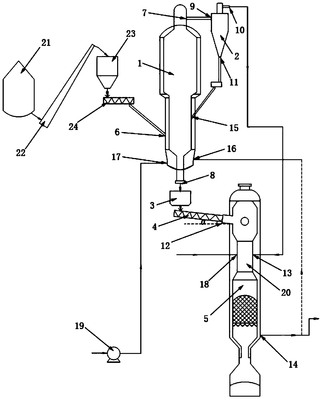
[0049] In further embodiments of the present invention, please continue to refer to figure 1 As shown, the downdraft fixed-bed gasifier 5 is also provided with a second gasification agent inlet 18, and the second gasification agent inlet 18 is used for introducing air or oxygen-enriched air.

[0050] In a further embodiment of the present invention, the downdraft fixed-bed gasifier 5 includes a throat section 20 , and the inlet of the second gasification agent 18 and the inlet of the pyrolysis gas 13 are located at the throat section 20 .

[0051] In a further embodiment of the present invention, an angle α is formed between the first screw feeder 4 and the coke inlet 12, and the angle range of the angle α is between 0° and 60°. Preferably, the biomass pyrolysis fluidized bed gasifier 1 and the downdraft fixed bed gasifier 3 are connected through a coke hopper 3 and a first screw feeder 4 .

[0052] In a further embodiment of the present invention, it also includes: a biomass...

Embodiment 1

[0061] Take a combined bed biomass gasification system with a daily biomass processing capacity of 85 tons as an example, which is used for internal combustion engine power generation. Biomass is corn stover. The design parameters of the pyrolysis-gasification reaction device are as follows:

[0062] Matching fuel gas power generation: 3MW

[0063] Feed biomass water content: 20%;

[0064] Feed biomass particle size: <10mm;

[0065] Fluidized bed pyrolysis furnace temperature: 450°C;

[0066] Downdraft fixed bed gasification temperature: 800°C;

[0067] Operating pressure: 10kPa;

[0068] Calorific value of fuel: 3000kCal / kg;

[0069] Gasification agent: normal temperature air.

[0070] after treatment

[0071] Total gasification efficiency: 84.1%;

[0072] Calorific value of fuel gas: ~6000kJ / Nm3;

[0073] Dust content in gas: less than 5g / Nm3;

[0074] Tar content in gas: less than 100mg / Nm3, preferably 50mg / Nm3;

[0075] Decombustion gas volume: 6000Nm3 / h;.

[...


PUM

PropertyMeasurementUnit
Particle sizeaaaaaaaaaa
Calorific valueaaaaaaaaaa

Abstract

The invention discloses a novel combined bed biomass gasification system and a method thereof. The novel combined bed biomass gasification system comprises a biomass pyrolysis fluidized bed gasification furnace, a cyclone separator, a coke hopper, a first screw feeder and a downdraft fixed bed gasification furnace; the biomass pyrolysis fluidized bed gasification furnace is provided with a biomassinlet, a crude pyrolysis gas outlet and a coke outlet; the cyclone separator is provided with a crude pyrolysis gas inlet, a pyrolysis gas outlet and an ash outlet; the coke hopper is communicated with the coke outlet; the first screw feeder is communicated with the coke hopper; the downdraft fixed bed gasification furnace is provided with a coke inlet, a pyrolysis gas inlet and a fuel gas outlet, and the coke inlet is communicated with the first screw feeder. The novel combined bed biomass gasification system and the method thereof effectively reduce the tar content in crude fuel gas, effectively improve the gasification efficiency and realize the efficient and clean utilization of biomass.

Description

technical field [0001] The invention relates to the technical field of biomass treatment, in particular to a novel combined bed biomass gasification system and a method thereof. Background technique [0002] Biomass energy is the solar energy converted and stored by green plants through photosynthesis. It is an important renewable resource and the earliest energy actively used by humans. It has played an important role in the history of human civilization. So far, biomass energy is still the fourth primary energy consumption in the world, and it is widely used in rural areas of our country and developing countries. The average annual output of crop straw in my country is about 700 million tons, of which about 1 / 3 of the straw is burned directly in the field, causing waste of resources and air pollution. Therefore, the development of distributed biomass gasification in units of villages and towns Power generation technology is an effective way to solve these problems. Biomas...

Claims


Application Information

Patent Timeline
IPC IPC(8): C10J3/66C10J3/84C10J3/72
CPCC10J3/66C10J3/721C10J3/84C10J2300/092
Inventor 崔洁宛政茹斌孙立曾志伟郭泗勇程文丰
Owner SHANGHAI ELECTRICGROUP CORP
Why Eureka
Try Eureka