Snapshot grating spectrometer
A grating spectrometer and snapshot technology, which is applied in the field of spectroscopic instruments, can solve the problems of high cost, complicated device processing, and the inability of snapshot grating spectrometer to simultaneously meet the requirements of wide-spectrum measurement, high luminous flux and high resolution, and achieve high cost performance and high resolution. Broad Spectrum Measurements, Effects of Size Reduction
- Summary
- Abstract
- Description
- Claims
- Application Information
AI Technical Summary
Problems solved by technology
Method used
Image

Examples
Embodiment 1
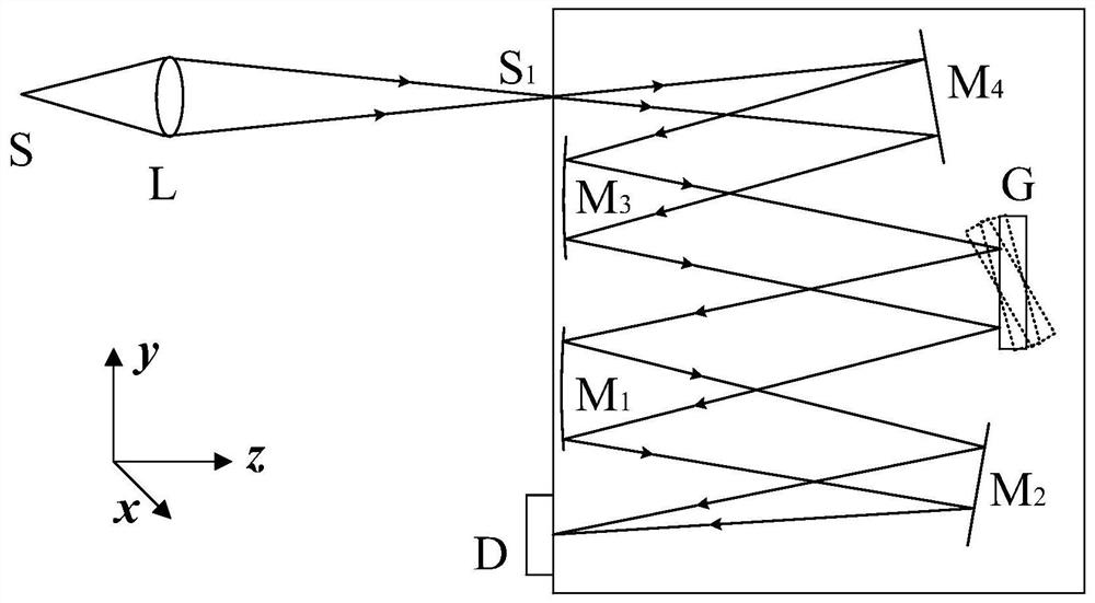
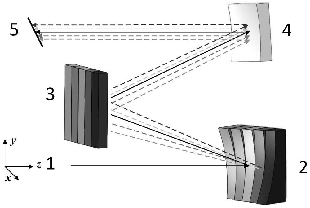
[0078] Adopt image slicer (21) as collimating mirror among the present embodiment, spherical mirror (41) is as imaging mirror, dispersion element is common plane blazed grating (31), and grating constant is 600lp / mm, and blaze angle is 10.37 °, detects The device is an area array CCD (51), and the system simulation structure diagram is as follows Image 6 shown.
[0079] The number n of the spherical sub-mirrors of the image splitter is set to 5, and the wavelength range is 200-1000nm.
[0080] One method that can be used is to divide the wave band evenly, and divide the wavelength into five groups. 840nm), 920nm (840–1000nm).
[0081] attached Figure 5 shows how a composite blazed grating works, where i n is the incident angle, θ bn is the diffraction angle, θ Bn For the shining angle. In order to facilitate the reception of the detector, each sub-grating can have the same diffraction angle for the main light of the central wavelength of different bands, and the incid...
Embodiment 2
[0092] Present embodiment adopts image splitter (21) as collimating mirror, spherical mirror (41) as imaging mirror, dispersion element is composite blazed grating (32), grating constant is 600lp / mm, detector is area array CCD (51) , the system simulation structure diagram is as follows Figure 11 shown.
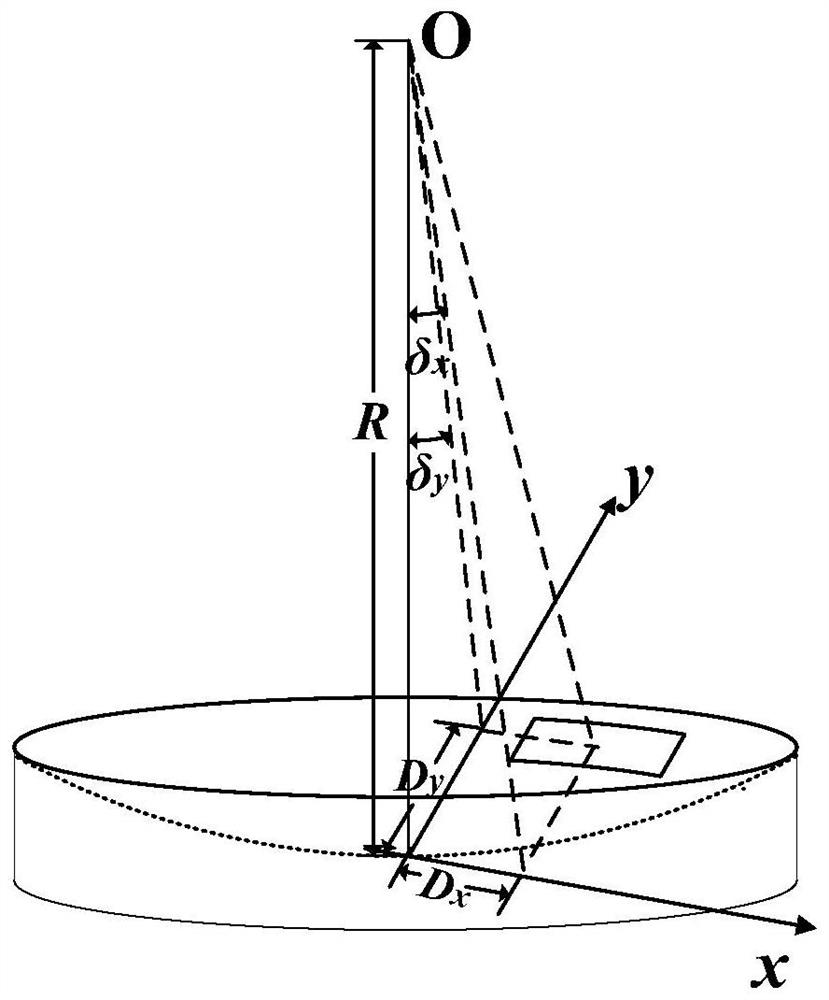
[0093] Set the number n of the spherical sub-mirrors of the image splitter to 5, for the wavelength range of 200-1000nm, the focal length of the image splitter and the imaging mirror are both 100mm, the incident slit is 20μm, and the chief ray targets the image splitter The two-dimensional deflection angle (δ x ,δ y ) is (0°, 7.5°), the incident angle of the chief ray to the composite blazed grating is 5°, and the main parameters of the designed optical path are shown in Table 2.
[0094] The main design parameters of the optical path of the second embodiment of Table 2
[0095] Band range Δλ 200–360nm 360–520nm 520–680nm 680–840nm 840–1000nm gr...
Embodiment 3
[0098] Present embodiment adopts as collimating mirror like splitter (21), like splitter (42) as imaging mirror, dispersion element is composite blazed grating (32), and grating constant is 600lp / mm, and detector is area array CCD (51), the system simulation structure diagram is attached Figure 13 shown.
[0099] Set the number n of spherical sub-mirrors of the image splitter to 5, for the wavelength range of 200-1000nm, the incident slit is 20μm, the sub-mirror of the image splitter is a spherical mirror with a focal length of 100mm, and the two-dimensional The deflection angle parameters are shown in Table 2.
[0100] The two-dimensional deflection angle parameter of image slicer in the third embodiment of table 3
[0101]
[0102] The spectral line diagram of embodiment three is attached Figure 14 As shown, only the center wavelength and two edge wavelengths of each band are used in the ZEMAX simulation, and each row from top to bottom represents 840–1000nm, 680–840...
PUM
 Abstract
Description
Claims
Application Information
PatSnap Eureka turns technology decisions into work you can execute. Powered by our Innovation Knowledge Graph, it runs expert workflows across engineering, life sciences, materials and intellectual property. Get your review-ready output in minutes.


