Laser machining apparatus laser machining method and computer-readable recording medium storing laser machining program
A laser processing method and laser processing technology, which are applied to lasers, metal processing, laser welding equipment, etc., can solve the problems of not considering the effect of thermal lens and the decline of processing quality, and achieve the effect of suppressing adverse effects
- Summary
- Abstract
- Description
- Claims
- Application Information
AI Technical Summary
Problems solved by technology
Method used
Image
Examples
Embodiment 1
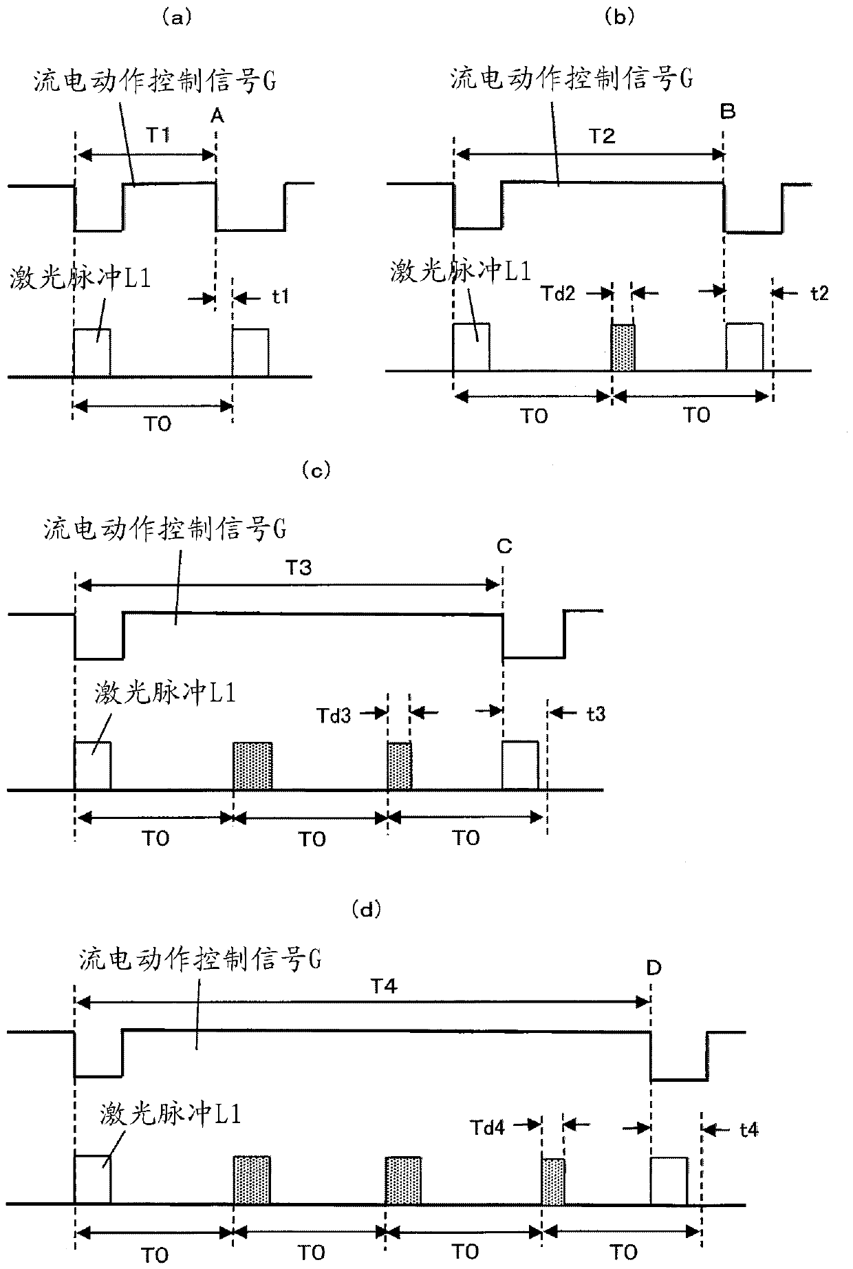
[0035] Figure 5 It is a block diagram of the laser drilling apparatus which becomes Example 1 of this invention. Concerning the respective components and connecting lines, those considered to be necessary for the description of the present embodiment are mainly shown, and not all of the components and connecting lines necessary for the laser drilling device are necessarily shown. The same applies to the block diagram of the laser drilling device shown below.
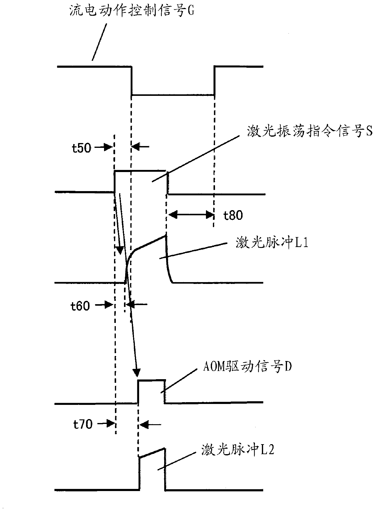
[0036] exist Figure 5 Among them, 1 is a printed circuit board to be processed placed on a table not shown in the figure, 2 is a laser oscillator that oscillates a laser pulse L1, and 3 is an AOM that directs the laser pulse L1 output from the laser oscillator 2 in the processing direction. The deflected laser deflection unit 4 is a light that is rotationally driven so as to irradiate the punching position of the printed circuit board 1 according to the processing data by changing the laser irradiation position of th...
Embodiment 2
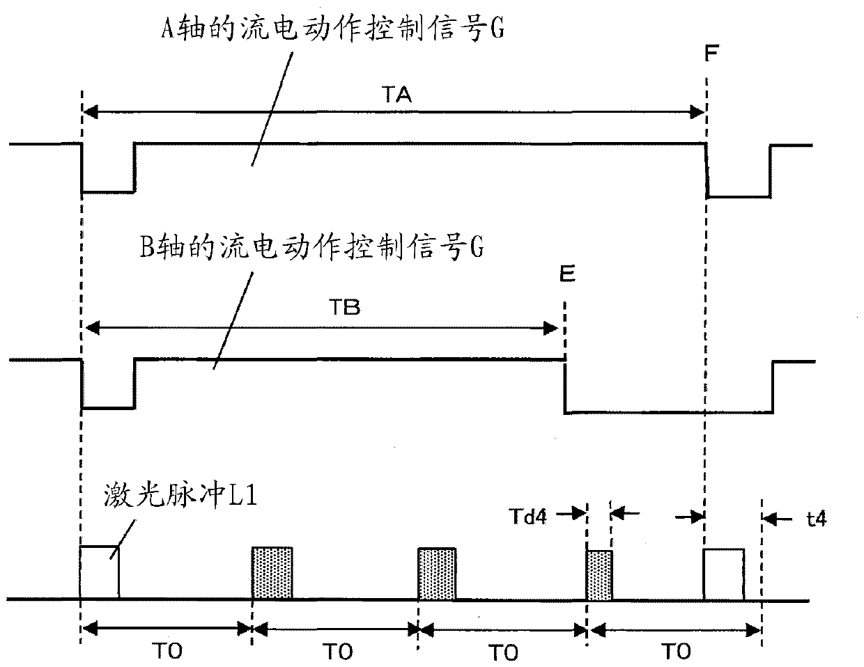
[0074] Next, Embodiment 2 of the present invention will be described. Figure 7 It is a block diagram of a laser drilling device serving as the second embodiment. for with Figure 5 Add the same number for the same content. This laser drilling device is a so-called 2-axis laser drilling device that achieves high speed by performing processing at two positions in parallel. Figure 8 is for illustration Figure 7 The timing diagram of the oscillation of the laser pulse L1 in the laser drilling device.
[0075] exist Figure 7 Among them, 1-A and 1-B are printed substrates to be processed respectively. Hereinafter, the system for processing the printed circuit board 1 -A is referred to as the A axis, and the system for processing the printed circuit board 1 -B is referred to as the B axis. 12 is a beam splitter that splits the laser pulse oscillated from the laser oscillator 2 in two directions, and 3-A and 3-B respectively deflect the laser pulse output from the beam split...
Embodiment 3
[0086] Next, Embodiment 3 of the present invention will be described. Figure 9 It is a block diagram of the laser drilling apparatus used as Example 3. for with Figure 5 , Figure 7 Add the same number for the same content. This laser drilling device is a so-called 4-axis laser drilling device that achieves high speed by performing processing at four positions in parallel. Figure 10 with Figure 11 is for illustration Figure 9 Timing diagram of the oscillation of the laser pulse in the laser drilling device.
[0087] exist Figure 9 Among them, 1-C to 1-F are printed circuit boards to be processed respectively. Hereinafter, the systems for processing the printed circuit boards 1 -C to 1 -F are respectively referred to as C axis to F axis. 3-CD and 3-EF are AOMs that respectively deflect the laser pulses output from the beam splitter 12 from the non-processing direction to the processing direction, and the laser deflection parts 3-CD and 3-EF can simultaneously defl...
PUM
 Abstract
Description
Claims
Application Information
 - R&D Engineer
- R&D Manager
- IP Professional
- Industry Leading Data Capabilities
- Powerful AI technology
- Patent DNA Extraction
Browse by: Latest US Patents, China's latest patents, Technical Efficacy Thesaurus, Application Domain, Technology Topic, Popular Technical Reports.
© 2024 PatSnap. All rights reserved.Legal|Privacy policy|Modern Slavery Act Transparency Statement|Sitemap|About US| Contact US: help@patsnap.com


