Integrated forging and forming method for reactor pressure vessel barrel flange adapter tube section

A technology for cylinder flanges and pressure vessels, which is applied to engine components, mechanical equipment, etc., can solve the problems of reducing the safety of cylinder flange joints, poor quality stability in complex stress areas, and increasing the workload of in-service inspections. Achieve the effects of shortening the equipment manufacturing cycle, solving the anisotropy of forgings, and avoiding structural defects in forgings

Active Publication Date: 2019-08-06
SHANGHAI XINMIN DONGTAI HEAVY FORGING
View PDF7 Cites 11 Cited by
  • Summary
  • Abstract
  • Description
  • Claims
  • Application Information

AI Technical Summary

Problems solved by technology

Due to the limitation of manufacturing technology and manufacturing process, the existing cylinder flange connecting section is to splice and weld four connecting pipes one by one along the radial direction of the cylinder to the cylinder wall of the cylinder. This development process is simple and easy. However, due to the presence of four circular welds on the components, the safety of the flange connection section of the cylinder body is reduced, and the workload of in-service inspection is increased at the same time
Although with the development of material science, the performance of welding materials has been greatly improved, and new welding processes have emerged in an endless stream, but the structure welded by splicing can not always form a complete metal flow line, because the nuclear reactor pressure vessel cylinder is in In the extremely harsh operating environment, and long-term work under the conditions of high temperature, high pressure and neutron irradiation, this splicing structure is extremely prone to fatigue, creep and damage, which brings very dangerous safety problems and limits the development of nuclear power ; and the welding process is very complicated, the welding cycle is long, and the quality stability of the complex stress area is poor, which directly leads to low yield and a substantial increase in manufacturing costs

Method used


Image

  • Integrated forging and forming method for reactor pressure vessel barrel flange adapter tube section

Examples


Embodiment Construction

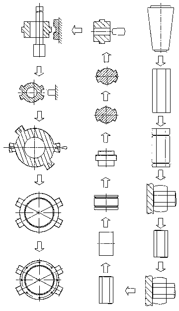
[0044] figure 1 It is a flow chart of the process steps of the overall forging forming method of the flange connection section of the present invention. In each step of the process method, the initial forging temperature of the steel ingot forging is 850°C, and the final forging temperature of the steel ingot forging is 1270°C. When the temperature is lower than 850°C, the forging should be re-sent into the heating furnace for heating to 1270°C, so that the forging temperature of the forging should be kept within the range of 850°C-1270°C. Its steps of the forging forming method of the present embodiment are as follows:

[0045] Steel ingot heating: the material of the steel ingot in this embodiment is 508-3 steel, and the amount of steel ingot is 100 tons. First, the steel ingot is heated in sections, and the steel ingot is put into the heating furnace for heating to improve the plasticity of the metal, make it easy to flow and form and obtain a good forged structure, and ch...


PUM


Abstract

The invention discloses an integrated forging and forming method for a reactor pressure vessel barrel flange adapter tube section. The integrated forging and forming method for the reactor pressure vessel barrel flange adapter tube section comprises the steps of (1) heating a steel ingot, and pressing the steel ingot to obtain an eight-edge prism steel billet; (2) blanking a forging billet: cutting a head part and a tail part of the eight-edge prism steel billet so as to obtain an eight-edge prism forging billet; (3) upsetting and drawing the forging billet: upsetting and drawing out the forging billet; (4) carrying out upsetting and rolling: upsetting and rolling the forging billet to obtain a short cylindrical forging billet; (5) carrying out marking and dividing in the circumferential direction: cutting two marking and dividing grooves at two ends of the short cylindrical forging billet; (6) carrying out rolling and necking: forming an adapter tube billet with a convex ring in the middle section; (7) carrying out marking and dividing in the axial direction: cutting four axial dividing grooves arranged along the axial direction; (8) circularly pressing a hemline; (9) marking anddividing a hemline boss: forming four sections of bosses on a hemline adapter tube billet; (10) punching a main hole; (11) carrying out chambering and forming; (12) carrying out shaping and chambering; (13) punching an adapter tube hole; (14) carrying out heat treatment after forging; (15) roughly machining the billet; (16) carrying out quenching; (17) carrying out hardening and tempering; and (18) processing a finished product. According to the method, integrated forming and forming is realized, the structure is uniform and dense, and a metal flow line is complete.

Description

technical field [0001] The invention relates to a forging forming process of large-scale nuclear power structural parts, in particular to an integral forging forming process of a reactor pressure vessel (abbreviated as RPV) shell shell flange connection section. Background technique [0002] Nuclear power is a clean and safe energy source. Nuclear power will not emit huge amounts of pollutants into the atmosphere like fossil fuel power generation. Nuclear power generation will not cause air pollution and its environmental impact is small. The energy density of nuclear fuel used in nuclear power generation is compared Fossil fuels are millions of times higher, so the fuel used in nuclear power plants is small and easy to transport and store. [0003] The reactor pressure vessel (RPV for short) is at the core of the primary circuit of the nuclear island of the entire pressurized water reactor nuclear power plant, and belongs to the first-class equipment of nuclear safety. Its...

Claims


Application Information

Patent Timeline
Patent Type & Authority Applications(China)
IPC IPC(8): B21K1/14
CPCB21K1/14
Inventor 马武江陈飞宣禹澄何龙李志坤杨婧婧任茂荣
Owner SHANGHAI XINMIN DONGTAI HEAVY FORGING
Why Eureka
Try Eureka