
Denitrification method using decomposing furnace and decomposing furnace

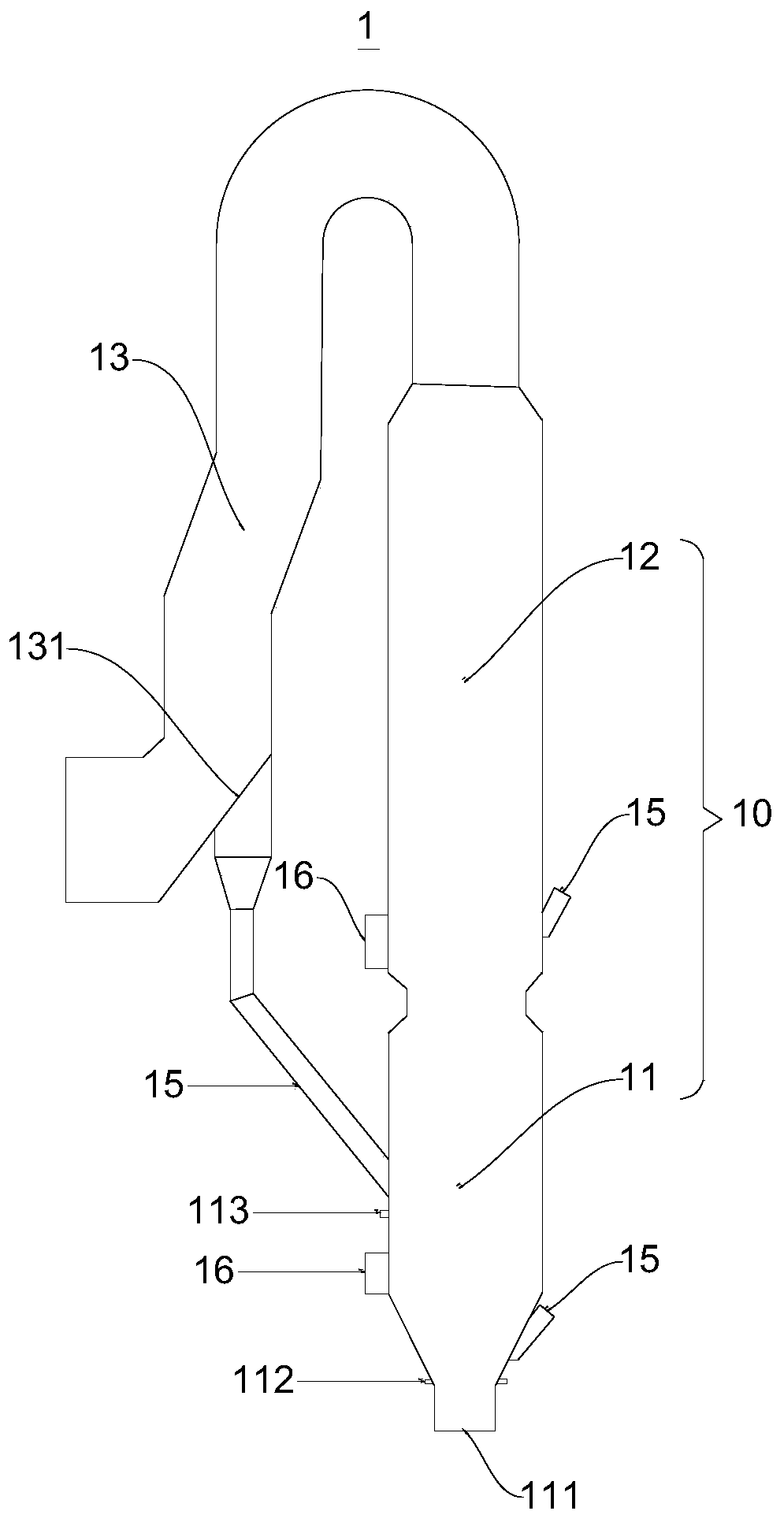
A calcining furnace and denitration technology, applied in the field of cement industry, can solve the problems of unsatisfactory denitration effect of calcining furnace, high cost, complicated equipment, etc., and achieve the effect of improving material utilization rate, reducing the risk of skinning, and reducing production cost.

Inactive Publication Date: 2019-08-06
CHENGDU JINGLONG TECH
View PDF4 Cites 2 Cited by
  • Summary
  • Abstract
  • Description
  • Claims
  • Application Information

AI Technical Summary

Problems solved by technology

During the process of preparing cement raw meal by using the rotary kiln, a large amount of waste gas containing nitrogen oxides will be discharged. Nitrogen oxides are extremely harmful to the natural environment. It needs to be reduced to nitrogen to reduce the hazards. In order to meet this demand, it has been Most of the calciners have the function of reducing nitrogen oxides, but the denitrification effect of the existing calciner denitrification methods and the supporting calciner is not ideal, and the equipment is too complicated, there is a risk of crusting and material accumulation, and the operation is inconvenient At the same time, the energy consumption is high and the cost is high. Therefore, it is necessary to propose an efficient and easy method for denitrification using a calciner, and a calciner suitable for this method

Method used


Image

  • Denitrification method using decomposing furnace and decomposing furnace

Examples


Embodiment 1

[0051] This embodiment provides a method for denitrification using a decomposition furnace, which includes the following steps:

[0052] Pulverized coal for reduction is injected from the lower end of the decomposition furnace and burned under anoxic conditions to prepare an oxygen-deficient reducing atmosphere, and pulverized coal for oxygen consumption is injected from the upper end of the decomposition furnace and burned to consume part of the oxygen at the upper end of the reducing atmosphere. The mass ratio of pulverized coal for reduction to pulverized coal for oxygen consumption is 4:1.

[0053] Inject two tertiary air into the calcining furnace, one of which is introduced from the lower end of the calcining furnace, and the other is introduced from the upper end of the calcining furnace. The volume ratio of the tertiary air entering the lower end to the tertiary air entering the upper end is 5:95.

[0054] The preheated cement raw meal is put into the decomposition furnace f...

Embodiment 2

[0059] This embodiment provides a method for denitrification using a decomposition furnace, which includes the following steps:

[0060] Pulverized coal for reduction is injected from the lower end of the decomposition furnace and burned under anoxic conditions to prepare an oxygen-deficient reducing atmosphere, and pulverized coal for oxygen consumption is injected from the upper end of the decomposition furnace and burned to consume part of the oxygen at the upper end of the reducing atmosphere. The mass ratio of pulverized coal for reduction to pulverized coal for oxygen consumption is 1:1.

[0061] Inject two tertiary air into the calcining furnace, one of which is introduced from the lower end of the calcining furnace, and the other is introduced from the upper end of the calcining furnace. The volume ratio of the tertiary air entering the lower end to the tertiary air entering the upper end is 45:55.

[0062] The preheated cement raw meal is put into the decomposition furnace ...

Embodiment 3

[0067] This embodiment provides a method for denitrification using a decomposition furnace, which includes the following steps:

[0068] Pulverized coal for reduction is injected from the lower end of the decomposition furnace and burned under anoxic conditions to prepare an oxygen-deficient reducing atmosphere, and pulverized coal for oxygen consumption is injected from the upper end of the decomposition furnace and burned to consume part of the oxygen at the upper end of the reducing atmosphere. The mass ratio of pulverized coal for reduction to pulverized coal for oxygen consumption is 2.6:1.

[0069] Inject two tertiary air into the calcining furnace, one of which is introduced from the lower end of the calcining furnace, and the other is introduced from the upper end of the calcining furnace. The volume ratio of the tertiary air entering the lower end to the tertiary air entering the upper end is 1:10.

[0070] The preheated cement raw meal is put into the decomposition furnace...


PUM


Abstract

The invention relates to a denitration method using a decomposing furnace and the decomposing furnace. The method comprises the following steps: coal powder is injected from the lower end of the decomposing furnace and combusted under an anoxic condition to form an anoxic reducing atmosphere, and coal powder is injected from the upper end of the decomposing furnace and combusted to consume part ofoxygen at the upper end of a reducing atmosphere; tertiary air is sprayed into the decomposing furnace in streams to make the air excess coefficient be 0.3-0.6; a cement raw material is respectivelyput into the decomposing furnace from a plurality of feeding ports for carbonate decomposition, so that the temperature at the reducing atmosphere is 900-1100 DEG C; exhaust gas is introduce from thatbottom end of the decomposing furnace for reduction denitration, and the reaction time is 0.5 to 1.2 seconds; and insufficiently combustible solid materials are guided to the decomposing furnace by refluxing with a reflux ratio of 20-45%. The denitration method using the decomposing furnace is simple and easy to operate, can reduce 60-85% of nitrogen oxides generated by a rotary kiln to nitrogen,has high reduction efficiency, effectively reduces the harm to the natural environment, does not affect the decomposition of carbonate in cement raw materials, can fully utilize materials, and savescost.

Description

Technical field [0001] The invention relates to the field of cement industry, and in particular to a method for denitrification using a calciner and a calciner. Background technique [0002] Decomposing furnace is a very frequently used equipment in the cement industry. Currently, there are various types of decomposition furnaces, such as spraying type, swirling type, swirling-spraying type, pipeline suspension type, etc., to cooperate with various decomposition There are also many methods for decomposing the raw cement material used in the furnace. In the process of preparing cement raw meal by rotary kiln, a large amount of exhaust gas containing nitrogen oxides will be discharged. Nitrogen oxides are extremely harmful to the natural environment. It needs to be reduced to nitrogen to reduce the harm. In order to meet this demand, Most of the decomposition furnaces have the function of reducing nitrogen oxides, but the denitration effect of the existing denitrification furnaces...

Claims


Application Information

Patent Timeline
IPC IPC(8): C04B7/43F23C7/02F27D17/00B01D53/56B01D53/76
CPCC04B7/43F23C7/02F27D17/008B01D53/76B01D53/56B01D2251/204B01D2258/0283
Inventor 李昌勇
Owner CHENGDU JINGLONG TECH
Learn More