Coating paint mist treatment method

A treatment method and paint coating technology, applied in gas treatment, separation methods, biological treatment devices, etc., can solve the problems of high system maintenance requirements, frequent replacement, easy failure, etc., to achieve simple equipment maintenance, reduce the number of water changes, The effect of low processing cost

Inactive Publication Date: 2019-08-13
波态(上海)新材料科技有限公司
View PDF5 Cites 1 Cited by
  • Summary
  • Abstract
  • Description
  • Claims
  • Application Information

AI Technical Summary

Problems solved by technology

Due to the viscosity of paint powder, the traditional treatment process has the following disadvantages: ①The system has low treatment efficiency; ②The water spray tower is easy to block; ③The wet and dry separator is easy to block; ④The primary filter is easy to block and needs to be replaced frequently; ⑤Activated carbon The adsorption tower is easy to block, easy to fail, and needs to be replaced frequently; ⑥The system requires high maintenance
The current technology will produce a large amount of paint slag, and the organic solvent used for collection has a strong odor and is volatile, which is not friendly to the staff and the environment; the circulating water needs to be replaced and discharged frequently on a regular basis, which increases the operating cost and process complexity
Therefore, the existing paint mist treatment process has a great impact on the environment and high cost

Method used


Image

  • Coating paint mist treatment method
  • Coating paint mist treatment method

Examples


Embodiment 1

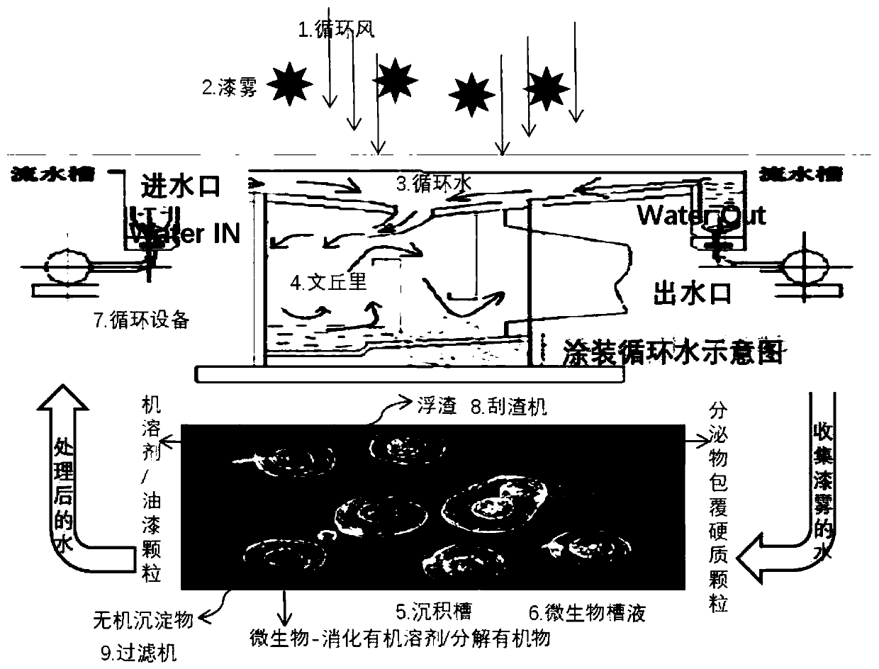
[0032] Such as figure 1 As shown, a schematic flow chart of a coating mist treatment method provided by an embodiment of the present invention is shown. The processing method includes:

[0033] (1) Coating paint mist 2 is carried by circulating air 1 into circulating water 3, washed by circulating water 3, and paint mist 2 enters the circulating water treatment system;

[0034] (2) The intercepted paint mist 2 enters the circulating water system, and the paint mist 2 is metabolized and decomposed by the microorganisms in the microbial tank 6, and a part of the remaining inorganic matter is wrapped by microbial secretions and floats on the surface of the tank liquid to be discharged. The machine 8 removes, and a part of the remaining inorganic matter is deposited at the bottom of the sedimentation tank 5 and is removed by the filter 9;

[0035] (3) The circulating water 3 in the circulating water treatment system washes the paint mist 2 and flows through the Venturi 4 and the sedime...

Embodiment 2

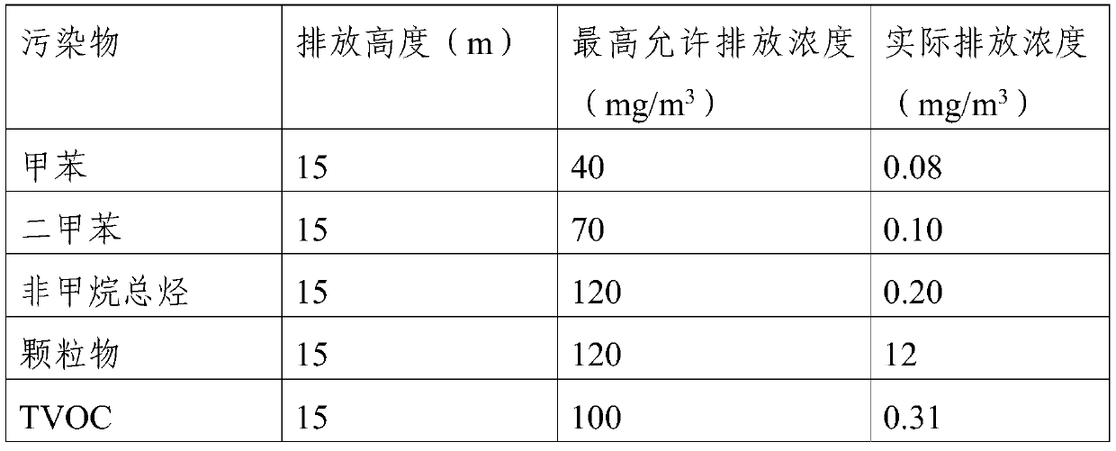
[0038] For example, if the method and system of Example 1 are run on a certain coating spraying line, the treatment cost can be saved by more than 80%, the exhaust gas can reach the standard stably, and the exhaust gas emissions are as follows:

[0039]

[0040] Waste residue emissions can be reduced by more than 90%:

[0041] By running this treatment method, the actual emission concentration of pollutants is far lower than the maximum allowable emission concentration standard.


PUM


Abstract

The embodiment of the invention discloses a coating paint mist treatment method. The coating paint mist treatment method includes the steps that coating paint mist is brought into Venturi circulatingwater through circulating air, wherein after being rinsed by the Venturi circulating water, the circulating air brings the paint mist into the Venturi circulating water, and the paint mist flows intoa circulating water treatment system along with the circulating water; the circulating water system is a special culture mixed microorganism system, paint mist collected by the circulating water includes organic solvents and organic macromolecular compounds and is metabolized by the microorganism system, after metabolism, part of residual inorganic pigments and a filler are coated by microorganismexcreta to float on the liquid surface of a circulating water storage tank and then are discharged through a slag scraping machine, and part of the residual inorganic pigments and filler deposit at the bottom of the circulating water storage tank and then are discharged through a filtration pump. By adopting the coating paint mist treatment method, discharging of paint slags and wastewater can begreatly reduced; pipeline clogging is reduced; the coating paint mist treatment method is friendly to the environment, and the cost is reduced.

Description

Technical field [0001] The invention relates to the technical field of waste gas treatment in the coating process, in particular to a coating paint mist treatment method. Background technique [0002] The main components of the exhaust gas generated by painting during the painting process are painting dust and volatilized benzene, toluene, xylene, etc. The random discharge has a greater impact on the surrounding environment, therefore, it needs to be discharged after certain treatment. [0003] The traditional treatment process mainly includes: painting waste gas, water spray tower, dry and wet separation, primary effect filter, activated carbon adsorption, discharge, etc. Due to the viscosity of paint powder, the traditional treatment process has the following shortcomings: ①The system treatment efficiency is low; ②The water spray tower is easy to block; ③The wet and dry separator is easy to block; ④The primary filter is easy to block and replace frequently; ⑤Activated carbon The...

Claims


Application Information

Patent Timeline
Patent Type & Authority Applications(China)
IPC IPC(8): B01D47/10B01D53/14C02F3/34C02F103/18
CPCB01D47/10B01D53/1425B01D53/1487B01D2247/04B01D2247/14B01D2258/0258C02F3/34C02F2103/18C02F2203/006
Inventor 郝胜利徐杰顾广新王林
Owner 波态(上海)新材料科技有限公司
Why Eureka
Try Eureka