Greenhouse plant humidity control equipment

A humidity control and plant technology, applied in the fields of botanical equipment and methods, agricultural machinery and equipment, gardening tools/equipment, etc., can solve problems such as affecting economic benefits, affecting plant quality, condensed water dripping, etc., to improve the survival rate, strengthen the Photosynthesis, the effect of high degree of automation

Inactive Publication Date: 2019-08-23
浦江县晶富农业科技有限公司
View PDF10 Cites 0 Cited by
  • Summary
  • Abstract
  • Description
  • Claims
  • Application Information

AI Technical Summary

Problems solved by technology

At present, the ceiling of the plant room is mostly flat, and the temperature of the plant room is lower than the room temperature, which will easily cause the temperature difference to cause the ceiling to condense, and the condensed water will drip on the plants, which will easily affect the quality of the plants.
At the same time, the temperature of the greenhouse is now artificially sensed, often resulting in improper temperature due to wrong information, resulting in reduced plant production and lack of nutrients during growth, directly affecting economic benefits

Method used


Image

  • Greenhouse plant humidity control equipment
  • Greenhouse plant humidity control equipment
  • Greenhouse plant humidity control equipment

Examples


Embodiment 1

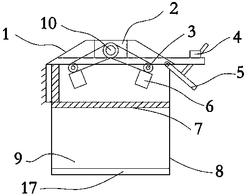
[0022] Such as Figure 1-5 As shown, the greenhouse plant humidity control equipment includes a shed body 8, a solar photovoltaic panel 1 is arranged on the top of the shed body 8, a lighting lamp 13 is embedded on the surface of the solar photovoltaic panel 1, a cavity 2 is provided under the solar photovoltaic panel 1, and the cavity 2 A fixed rod 10 is arranged inside, and the fixed rod 10 is connected with the rotating shaft 3 , and the exhaust fan 6 is connected with the lower part of the rotating shaft 3 . This device uses solar energy to convert other energy into the greenhouse. When the weather is relatively dark, the plants in the greenhouse cannot get enough sunlight. The lighting lamp can provide the plants with a certain amount of light, so that the plants can carry out normal photosynthesis. Lack of ventilation will lead to insufficient oxygen. The operation of the exhaust fan can speed up the air flow in the greenhouse to ensure sufficient oxygen concentration in...

Embodiment 2

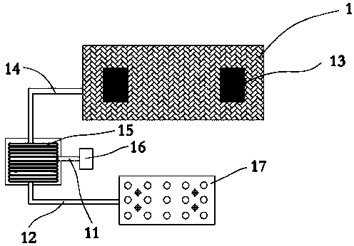
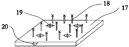
[0031] Such as Figure 1-5 As shown, the greenhouse plant humidity control equipment works as follows: when the temperature of the greenhouse is high, the controller 4 controls the rotation of the exhaust fan 6, and the exhaust fan 6 blows the air in the greenhouse out of the ventilation window 5 to speed up the air circulation. The water sprayed by the sprinkler 18 will cover the entire greenhouse to achieve the effect of sprinkling water to cool down. At the same time, the solar photovoltaic panel 1 converts heat energy into electrical energy and transmits it to the cold and heat exchanger 15 through the transmission pipe 14. The water in the water collection tank 16 passes through The cold heat exchanger 15 will heat up the water. After the temperature rises, the water will flow into the input port 20 and pass into the shower head 18. The warm water will not be sprayed out in the shower head 18, and a certain amount of heat will be generated to make the greenhouse a constant...


PUM


Abstract

The invention discloses greenhouse plant humidity control equipment, and belongs to the technical field of agricultural equipment. The greenhouse plant humidity control equipment comprises a greenhouse body, wherein a solar photovoltaic panel is arranged at the top of the greenhouse body; illuminating lamps are embedded on the surface of the solar photovoltaic panel; an empty cavity is formed in the lower part of the solar photovoltaic panel; a fixing rod is arranged in the empty cavity; the fixing rod is connected with rotary shafts; and exhaust fans are connected below the rotary shafts. Theheat preservation effect is good, the temperature can be kept within the optimal value, plants in the greenhouse can be irrigated and heated by solar energy, the humidity in the greenhouse can be controlled, designed nozzles have large spraying areas, and the efficiency is high.

Description

technical field [0001] The invention belongs to the technical field of agricultural equipment, in particular to a greenhouse plant humidity control equipment. Background technique [0002] The plant greenhouse is a frame-covered structure with excellent thermal insulation performance. Its appearance allows people to enjoy more beautiful plants. Generally, the plant greenhouse uses a bamboo structure or a steel structure support frame, covered with one or more layers of thermal insulation plastic film, thus forming a greenhouse space. The outer film can well prevent the loss of carbon dioxide produced by the growth of internal plants, so that the shed has a good thermal insulation effect. [0003] At present, with the continuous improvement of people's living conditions, people's requirements for the growth of plants are also getting higher and higher. Therefore, the requirements for heat preservation and safety of plant greenhouses are also getting higher and higher. At pr...

Claims


Application Information

Patent Timeline
Patent Type & Authority Applications(China)
IPC IPC(8): A01G9/24A01G7/04
CPCA01G7/045A01G9/24A01G9/243A01G9/247Y02P60/12Y02A40/25
Inventor 袁莉霞
Owner 浦江县晶富农业科技有限公司
Why Eureka
Try Eureka