
Heat management system and new energy automobile with same

A thermal management system and circulation system technology, applied in the field of electric vehicle thermal management system and its control, can solve the problems of complex structure, poor performance, large heat loss, etc.

Pending Publication Date: 2019-08-23
GREE ELECTRIC APPLIANCES INC
View PDF2 Cites 15 Cited by
  • Summary
  • Abstract
  • Description
  • Claims
  • Application Information

AI Technical Summary

Problems solved by technology

[0003] Patent document CN104748453A discloses a heat pump air-conditioning system for pure electric vehicles, which uses a common single-stage compression system. Under extreme working conditions, the compressor pressure ratio is too large, the exhaust temperature is too high, and the performance is poor
In addition, the system uses two heat exchangers outside the vehicle. The heating function uses the inter-system heat exchanger to perform a heat exchange with the refrigerant and the coolant, and then conducts a secondary heat exchange with the coolant and the interior of the vehicle, resulting in a large heat loss. , poor performance under extreme working conditions, complex structure and high cost
[0004] Patent document CN109466273A is a heat pump air-conditioning system that controls the temperature of the battery, but its system only manages the temperature of the passenger compartment and the battery, and does not comprehensively manage the heat of the electric vehicle, and cannot solve some special requirements in the operation of the air conditioner, such as heating The need for dehumidification and defrosting does not stop the heating, therefore, it is impossible to ensure the high efficiency operation of the air conditioning system while ensuring the interior property requirements of the car

Method used


Image

  • Heat management system and new energy automobile with same
  • Heat management system and new energy automobile with same
  • Heat management system and new energy automobile with same

Examples


Embodiment 1

[0056] This embodiment takes a heat management system for a motor vehicle as an example.

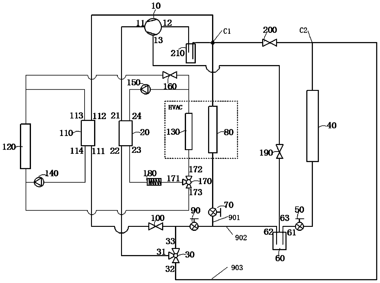
[0057] Such as figure 1 As shown, the electric vehicle thermal management system is mainly composed of a refrigerant circulation system and a coolant circulation system. The refrigerant cycle system is composed of a compressor 10 with intermediate air supply and enthalpy increase, a water-cooled intermediate heat exchanger 20, a first three-way proportional valve 30, an external heat exchanger 40, a first electronic expansion valve 50, a flasher 60, Second electronic expansion valve 70, interior heat exchanger 80, third electronic expansion valve 90, first solenoid valve 100, battery plate heat exchanger 110, fourth solenoid valve 190, second solenoid valve 200, gas-liquid separator 210 and the piping connecting them.

[0058] The compressor exhaust port 11 is connected to the first connection port 21 of the water-cooled intermediate heat exchanger, the second connection port 22 of the...

Embodiment 2

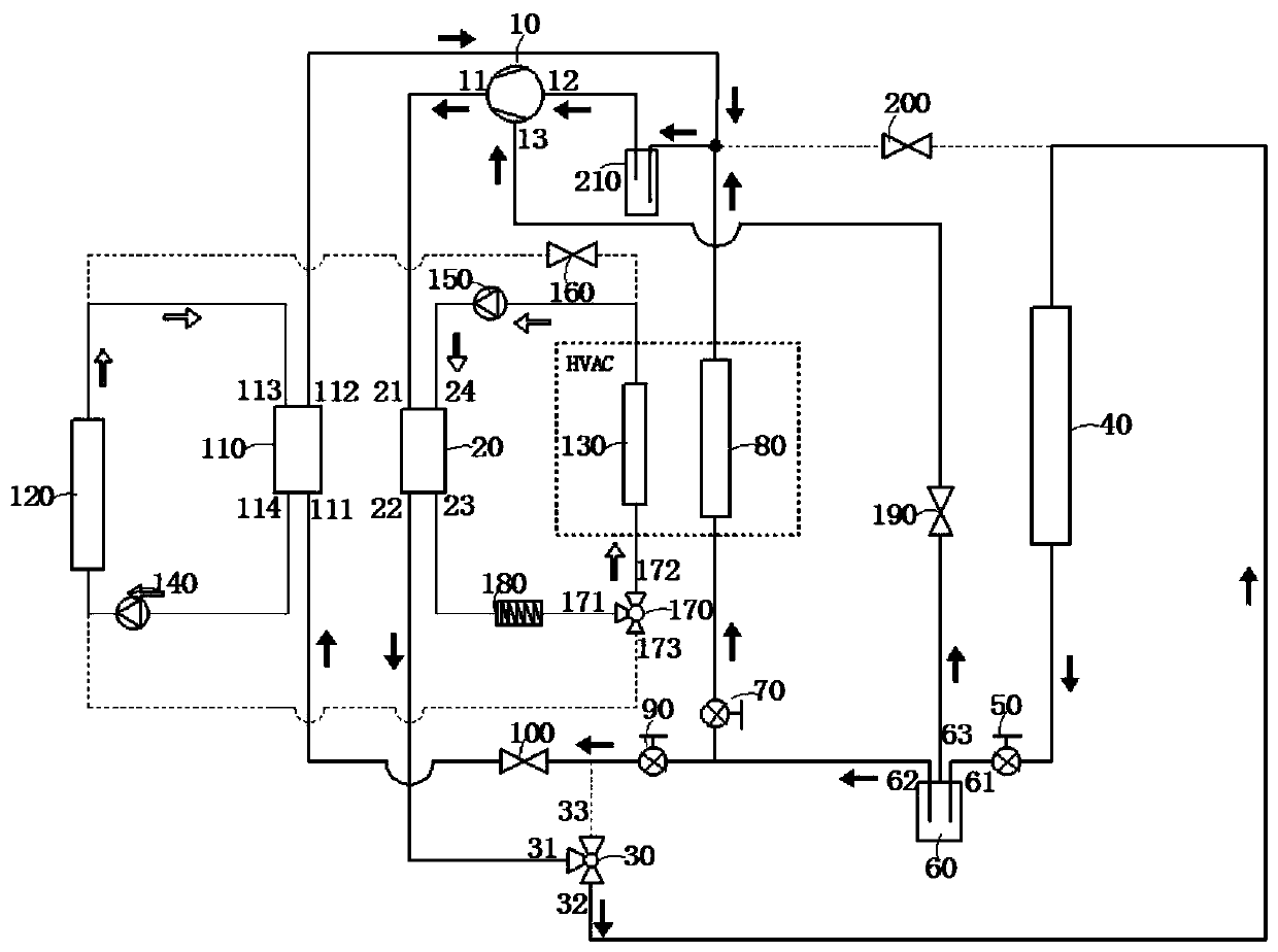
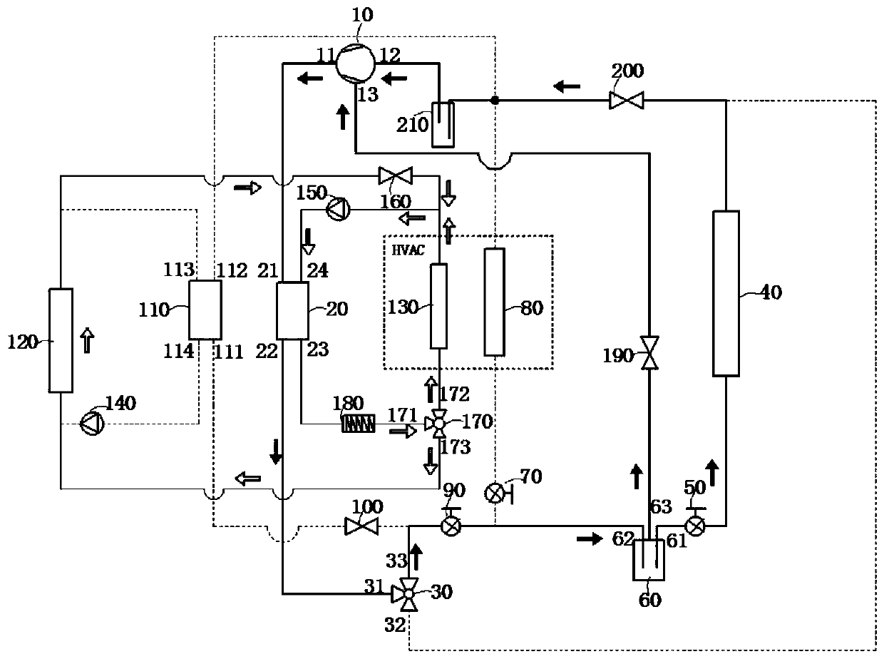
[0069] Based on the same inventive concept, combined with the above-mentioned scheme, such as Figure 1 to Figure 5 As shown, the present invention also provides a control method according to the above electric vehicle thermal management system.

[0070] Such as figure 2 As shown, in summer cooling conditions, the electric vehicle thermal management system of the present invention cools the passenger compartment and the battery at the same time.

[0071] The first port 31 of the three-way proportional valve is connected to the second port 32 of the three-way proportional valve, the first solenoid valve 100 is opened, the fourth solenoid valve 190 is opened, the second solenoid valve 200 is closed, and the first port 171 of the three-way proportional valve is connected to The flow ratio of the second interface 172 of the three-way proportional valve is 100%, and the third electromagnetic valve 160 is closed.

[0072]The high-temperature and high-pressure gaseous superheated ...

Embodiment 3

[0091] A new energy vehicle adopting the above energy management system and management method.

[0092] The foregoing embodiments have the following advantages:

[0093] 1. Through the use of a two-stage enthalpy-increasing compressor with an intermediate air supply port, a matching flasher and a two-stage throttling electronic expansion valve, a two-stage air supply enthalpy increasing system is realized to improve performance under extreme working conditions.

[0094] 2. Through the water-cooled condenser arranged between the compressor exhaust port and the external heat exchanger and the warm air core arranged in the HVAC air-conditioning box, the heat of the refrigerant in the heat pump system is indirectly transferred to the passenger compartment through the coolant Inside.

[0095] 3. The PTC liquid heater arranged in the coolant circulation serves as an auxiliary heating source for heating the passenger compartment and battery.

[0096] 4. Through the heater core and ...


PUM


Abstract

The invention provides an electric automobile thermal management system and a control method thereof and an automobile. An air conditioning system is composed of a refrigerant circulation system and acooling liquid circulation loop. The heat management system can be used for simultaneously cooling a passenger compartment and a battery during a summer working condition, simultaneously heating thepassenger compartment and the battery in a winter heating and heating supply condition, and simultaneously heating and defrosting the passenger compartment in a heating and dehumidifying working condition and a defrosting working condition; the comprehensive heat management capability of an electric automobile can be improved, the refrigerating efficiency of the air conditioning system is improved, the defrosting time is shortened, and the comfort of the air conditioning system is improved.

Description

technical field [0001] The invention relates to a heat management system, in particular to a heat management system and a control method for an electric vehicle. Background technique [0002] In the prior art, all automobiles are provided with an air conditioning system to manage the heat of the air environment in the compartment. The power battery of an electric vehicle also generates a lot of heat during the discharge process, and a rapid rise in battery temperature will affect the efficient operation of the battery. Therefore, thermal management of the power battery is also required. [0003] Patent document CN104748453A discloses a pure electric vehicle heat pump air-conditioning system, which adopts a common single-stage compression system. Under extreme working conditions, the compressor pressure ratio is too large, the exhaust temperature is too high, and the performance is poor. In addition, the system uses two heat exchangers outside the vehicle. The heating functi...

Claims


Application Information

Patent Timeline
IPC IPC(8): B60H1/00B60H1/04B60K1/00H01M10/613H01M10/615H01M10/6554H01M10/625
CPCB60H1/00392B60H1/04B60K1/00H01M10/613H01M10/615H01M10/6554H01M10/625B60K2001/005Y02E60/10
Inventor 李潇康宁
Owner GREE ELECTRIC APPLIANCES INC
Learn More