Coated proppant used for unconventional reservoir hydraulic fracturing as well as preparation and application of coated proppant

A technology for hydraulic fracturing and proppant, which is applied in drilling compositions, chemical instruments and methods, and production fluids, etc., can solve the problems of low-density corrosion resistance, high cost, interface damage, etc., and achieve enhanced connection and flowback. The effect of low rate and strong suspension ability

Active Publication Date: 2019-08-23
CHINA UNIV OF PETROLEUM (BEIJING)
View PDF3 Cites 11 Cited by
  • Summary
  • Abstract
  • Description
  • Claims
  • Application Information

AI Technical Summary

Problems solved by technology

Compared with the traditional proppant, the coated proppant has the characteristics of high strength, low density and corrosion resistance, but the resin film coated on the proppant is generally very t...

Method used


Image

  • Coated proppant used for unconventional reservoir hydraulic fracturing as well as preparation and application of coated proppant
  • Coated proppant used for unconventional reservoir hydraulic fracturing as well as preparation and application of coated proppant
  • Coated proppant used for unconventional reservoir hydraulic fracturing as well as preparation and application of coated proppant

Examples


Embodiment 1

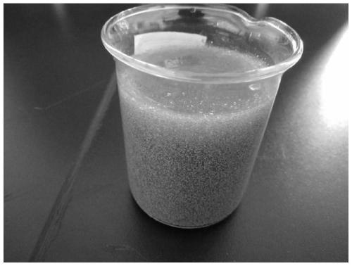
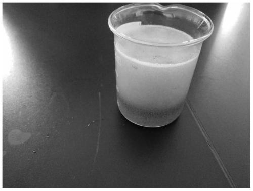
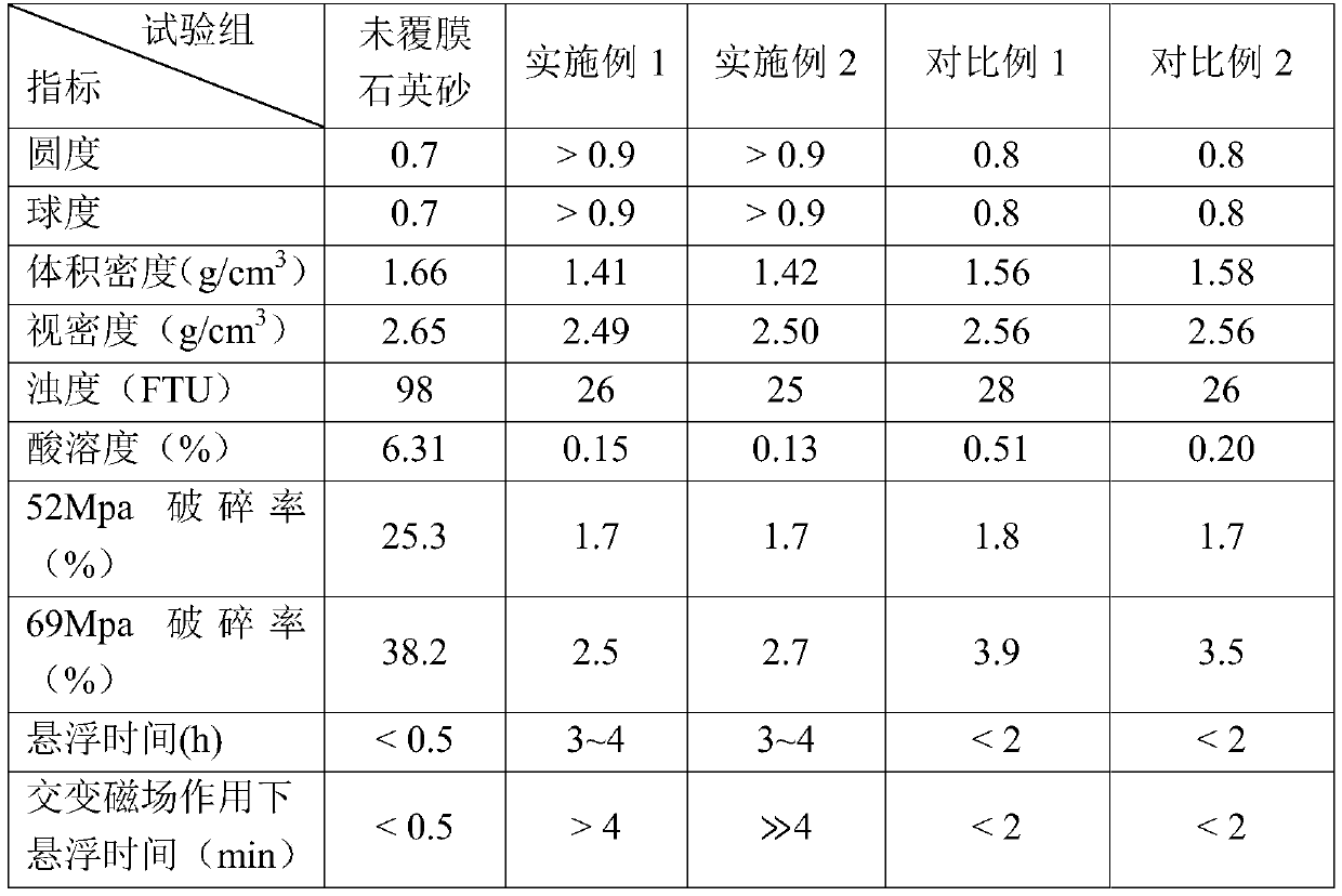
[0095] (1) Prepare the following materials: 100 parts of aggregate, 3 parts of polyurethane, 2 parts of polyol resin (polyester polyol polyurethane with a hydroxyl equivalent of 50-100), curing agent dibenzoyl peroxide (Foshan Shengyi Bio Technology Co., Ltd.) 1 part, catalyst 0.003 part, carbon quantum dot fluorescent particles 0.3 part, two-dimensional transition metal carbide 0.1 part, graphene 0.1 part, amine additive (ethylene diamine) 0.15 part.

[0096] (2) Heat the aggregate in step (1) to about 250°C, and pour it into a casserole mixing pot for sand mixing.

[0097] (3) Add the polyurethane in step (1) to the casserole mixing pot, and when the temperature drops below 210°C, add the curing agent for coating.

[0098] (4) Mix the polyol resin, carbon quantum dot fluorescent particles, two-dimensional transition metal carbide, and graphene uniformly, and heat to about 150°C for use.

[0099] (5) When the temperature of the mixing casserole drops to 80-150°C, the mixture in step ...

Embodiment 2

[0102] (1) Prepare the following materials: 100 parts of aggregate, 5 parts of epoxy resin e44 (Jiangyin Wanqian Chemical Co., Ltd.), 1 part of curing agent dibenzoyl peroxide (Foshan Shengyi Biotechnology Co., Ltd.), magnetic graphite 0.2 parts of olefin, 0.3 parts of polystyrene microspheres, 0.003 parts of catalyst, and 2.5 parts of surface modifier.

[0103] (2) Heat the aggregate in step (1) to about 250°C, and pour it into a casserole mixing pot for sand mixing.

[0104] (3) Add the epoxy resin in step (1) to the mixing casserole, and when the temperature drops below 210°C, add the curing agent to cover the film.

[0105] (4) When the temperature drops to 150°C, spray the surface modifier with water into the mixing casserole.

[0106] (5) When the temperature of the mixing casserole drops to 120°C, add the ultrapure aqueous solution of magnetic graphene and the ultrapure aqueous solution of polystyrene microspheres into the mixing casserole with hot air blowing, and the speed of...


PUM


Abstract

The invention provides a coated proppant used for unconventional reservoir hydraulic fracturing as well as preparation and application of the coated proppant. The proppant comprises the following components: A, particles with an amount of 70-99.99% based on a total weight of the proppant, and B, a nanoparticle-reinforced composite material coating layer which coats the surfaces of the particles and accounts for 0.01-30% of the total weight of the proppant, wherein the nanoparticle reinforced composite material comprises nanoparticles and a composite material. According to the coated proppant and preparation provided by the invention, nanoparticles are added into resin and polymer powder for reinforcement, so that affinity between the proppant coating film and aggregate is better, adhesionbetween the aggregate and the coating film is stronger, and the coated proppant has an intact surface and high sphericity after film coating.

Description

Technical field [0001] The present invention relates to the field of petrochemical industry. Specifically, the present invention relates to a film-coated proppant for hydraulic fracturing of unconventional reservoirs, and its preparation and application. Background technique [0002] With the depletion of conventional fossil energy sources such as oil and natural gas, the development and utilization of unconventional resources, especially shale gas, has attracted more and more attention. China has huge reserves of unconventional resources. Due to complex geological conditions and inefficient oil and gas collection methods, China's unconventional energy resources are obviously underutilized. [0003] Most unconventional reservoirs have the characteristics of low porosity and low permeability, and they can only be put into production after reservoir stimulation and reconstruction with the help of hydraulic fracturing. Hydraulic fracturing mainly increases the permeability of the for...

Claims


Application Information

Patent Timeline
IPC IPC(8): C09K8/80E21B43/267
CPCC09K8/805E21B43/267
Inventor 徐泉田守嶒盛茂张潘潘
Owner CHINA UNIV OF PETROLEUM (BEIJING)
Why Eureka
Try Eureka