Artificial borehole wall for preventing mudstone formation mud from being produced or channeling, forming method and well-completion structure

A technology of artificial well walls and rock formations, which is applied in wellbore/well components, drilling equipment, earthwork drilling and production, etc. It can solve the problems of reducing oil well productivity, time-consuming and laborious, and shortening the length of oil and gas production sections, so as to save working hours and costs , The construction process is simple, the production effect is good

Pending Publication Date: 2019-08-27
ANTON BAILIN OILFIELD TECH (BEIJING) CO LTD
View PDF9 Cites 1 Cited by
  • Summary
  • Abstract
  • Description
  • Claims
  • Application Information

AI Technical Summary

Problems solved by technology

However, this technical solution has the following disadvantages. First, it is necessary to carry out accurate logging work in advance to find out the location of the mudstone section, which is time-consuming and laborious. Second, in order to effectively seal the mudstone section, it is usually necessary to reserve enough The margin (that is, the length of the seal is greater than the length of the mudstone layer) leads to shortening of the oil and gas production section; thirdly, for the production section where the mudsto

Method used


Image

  • Artificial borehole wall for preventing mudstone formation mud from being produced or channeling, forming method and well-completion structure
  • Artificial borehole wall for preventing mudstone formation mud from being produced or channeling, forming method and well-completion structure
  • Artificial borehole wall for preventing mudstone formation mud from being produced or channeling, forming method and well-completion structure

Examples


Embodiment 1

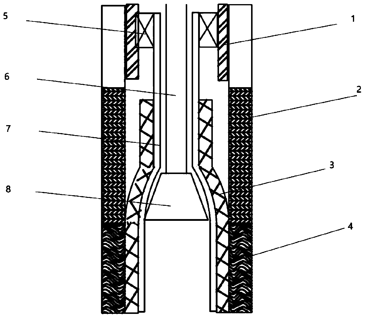
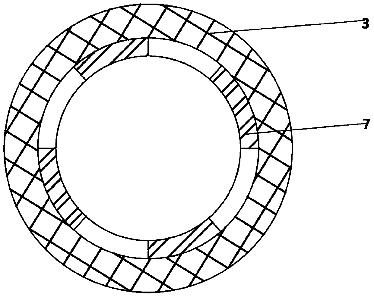
[0040] This embodiment provides a specific implementation method of using a physical expansion pipe to construct a porous medium artificial well wall that prevents the output or channeling of mudstone layer mud, including the following steps:

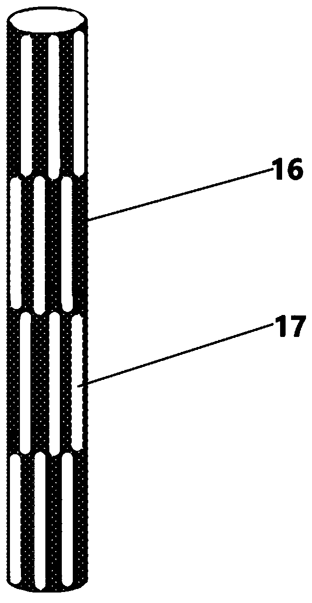
[0041] (1) Lower the expansion pipe whose outer layer is wrapped with a porous medium material layer into the wellbore. Specifically, the expansion tube is a cylindrical structure made of metal or alloy, and can expand outward along its radial direction. As a specific embodiment of the expansion tube, a structure similar to that of a heart stent can be used, for example, axial grooves are carved on the tube wall, and the structure can be expanded into a rhomboid network structure.

[0042] (2) After the expansion pipe is lowered to the specified position, use the mechanical force generated during the process of lifting the central pipe string (with expansion cone), or use the internal stress of the expansion pipe in the compressed state...

Embodiment 2

[0048] This embodiment provides a specific implementation method of using a self-expanding porous medium pipe string to form a porous medium artificial well wall to prevent mudstone layer mud production or channeling, including the following steps:

[0049] (1) Lowering into the wellbore a central pipe string with a solid expanded porous material attached to its outer surface; specifically, the solid expanded material can be artificial or natural fiber cotton bonded and tightly compacted by a water-soluble adhesive, Or a sponge.

[0050] (2) After the central pipe string is driven into the designated position, under the immersion action of the fluid in the wellbore, the solid expanded material expands and becomes larger and clings to the wellbore wall, forming a porous medium artificial wellbore wall. Specifically, the water-soluble adhesive gradually melts under the immersion of the wellbore fluid, and the tightly compacted fiber cotton or sponge absorbs water and expands und...

Embodiment 3

[0055] This embodiment provides a specific implementation method of adopting chemical pouring method to form a porous medium artificial well wall to prevent mudstone layer mud from outputting or channeling, including the following steps:

[0056] (1) Run the central pipe string into the wellbore;

[0057] (2) Inject cement slurry mixed with a foaming agent into the annular space between the central pipe string and the wellbore well wall; specifically, the quantity of the foaming agent mixed in the cement slurry should be such that the cement after solidification Pores forming a microchannel structure are preferred.

[0058] (3) After the cement slurry or high molecular polymer mother liquid is solidified, a porous medium artificial well wall is formed.

[0059] (4) After being put into production, when the mud fluid flows through the micropores in the porous media material of the artificial well wall, mud plugging can occur in the micropores and form mud cakes, thereby preven...


PUM

PropertyMeasurementUnit
Particle sizeaaaaaaaaaa
True densityaaaaaaaaaa
Thicknessaaaaaaaaaa

Abstract

The invention relates to a porous medium artificial borehole wall for preventing mudstone formation mud from being produced or channeling. The artificial borehole wall is of a tubular cavity structurewith the same shape as a shaft as a whole; the outer side of the artificial borehole wall is closely attached to a borehole wall of the shaft; and a microchannel is formed in the artificial boreholewall, and allows fluid to pass through and flow into the shaft and blocks mudstone formation mud liquid from passing through and flowing into the shaft and channeling. The artificial borehole wall hasthe advantages that firstly, mudstone sections do not need to be actively searched, and since the whole shaft is filled with the porous medium borehole wall, the porous medium borehole wall can automatically block mud migration of each mudstone section; secondly, the construction process is simple, the cost is low, and the process technologies of casing running, cement cementing, perforation andthe like involved in traditional casing perforation and completion technologies are not required so that the disadvantages of repeatedly tripping operation pipe columns are overcome, the working hoursare shortened and the cost is reduced; and thirdly, the original open hole wall for oil and gas production is not sealed, the seepage area is large, the production effect is good and the oil and gasoutput is high.

Description

technical field [0001] The invention belongs to the technical field of petroleum and natural gas exploitation, and relates to a technique for exploiting oil and gas reservoirs containing mudstone layers, in particular to a porous medium artificial well wall for preventing mudstone layer mud from being produced or channeling, and a mudstone layer mud prevention method. A method for forming an artificial well wall in a porous medium with production or channeling, and a well completion structure with the function of preventing the production or channeling of mudstone layer mud. Background technique [0002] Due to the overlapping phenomenon of mudstone layers and oil-gas-bearing sandstone layers in the formation, the wellbore of the production section drilled sometimes passes through one or more mudstone layers during the exploitation of oil and gas reservoirs. For this kind of open-hole well, if it is put into production directly at this time, the mud in the mudstone layer wil...

Claims


Application Information

Patent Timeline
IPC IPC(8): E21B33/13E21B17/00
CPCE21B17/00E21B33/13
Inventor 裴柏林张娟崔洪琪周祥
Owner ANTON BAILIN OILFIELD TECH (BEIJING) CO LTD
Why Eureka
Try Eureka