
Novel sprinkling quenching process applied to aluminum alloy plate

A technology of aluminum alloy plates and aluminum alloy materials, which is applied in the field of new spray quenching technology, can solve problems such as hindering the production of aluminum thick plates by spray cooling, large residual stress, etc., and achieve the effect of promoting high-quality production

Active Publication Date: 2019-09-06
西安兴航航空科技股份有限公司
View PDF4 Cites 2 Cited by
  • Summary
  • Abstract
  • Description
  • Claims
  • Application Information

AI Technical Summary

Problems solved by technology

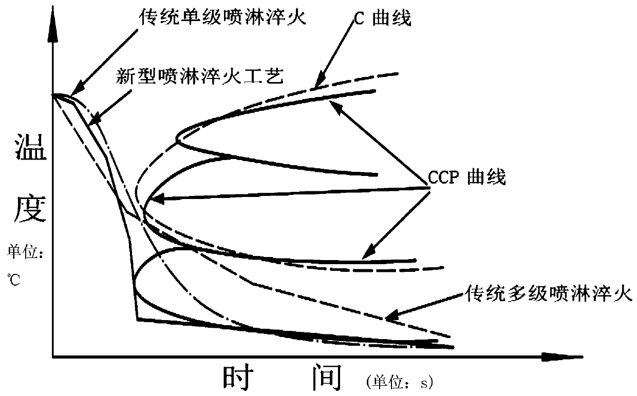
In the quenching process of aluminum thick plates, there are often multiple precipitation reaction stages, and the minimum critical rate of each stage is not consistent. The spray quenching process determined by the above two methods is likely to cause relatively large residual stress, which undoubtedly seriously hinders the aluminum alloy reaction process. Spray cooling production work for thick plates

Method used


Image

  • Novel sprinkling quenching process applied to aluminum alloy plate

Examples


Embodiment 1

[0035] AA7150 aluminum alloy (solution temperature: 480°C) is spray-quenched, and the plate thickness is 80 mm. There are three precipitation reaction stages in this material, which are P 1 Stage (455°C, 350°C) minimum critical cooling rate CR 1 is 10℃ / s, P 2 Stage (350°C, 255°C) minimum critical cooling rate CR 2 is 80℃ / s, P 3 Stage (255°C, 150°C) minimum critical cooling rate CR 3 300°C / s;

[0036] Therefore, the cooling curve of the aluminum thick plate is designed to be 5 sections, that is, Q 0 Stage (480°C, 455°C) cooling rate is air cooling rate CR air , Q 1 , Q 2 , Q 3 The temperature ranges of the stages are (455°C, 350°C), (350°C, 255°C), (255°C, 150°C), Q 1 The stage cooling rate is 10°C / s, Q 2 The stage cooling rate is 80°C / s, Q 3 The stage cooling rate is 300°C / s, Q 4 Stage (150°C, room temperature) cooling rate is air cooling rate CR air ;

[0037] When industrial tap water at 20°C is used as the cooling medium, there will be no water spray from the ...

Embodiment 2

[0039] AA2618 aluminum alloy (solution temperature: 530°C) plate is quenched, with a plate thickness of 80mm. There are two precipitation reaction stages in this material, which are P 1 Stage (390°C, 280°C) minimum critical cooling rate CR 1 is 20℃ / s, P 2 Stage (280°C, 170°C) minimum critical cooling rate CR 2 100°C / s;

[0040] Therefore, the cooling curve of the aluminum thick plate is designed into 4 sections, that is, Q 0 Stage (530°C, 390°C) cooling rate is air cooling rate CR air , Q 1 , Q 2 The temperature ranges of the stages are (390°C, 280°C), (280°C, 170°C), Q 1 The stage cooling rate is 20°C / s, Q 2 The stage cooling rate is 100°C / s, Q 3 Stage (170°C, room temperature) cooling rate is air cooling rate CR air ;

[0041] When industrial tap water at 20°C is used as the cooling medium, there is no water spraying from the nozzle at 0-14s, no water spraying at the nozzle and forced convection air cooling is used at 14s-19.5s, and the nozzle pressure is 100kPa at...


PUM


Abstract

The invention discloses a novel sprinkling quenching process applied to an aluminum alloy plate. According to the temperature ranges of a plurality of evolution reaction stages in an aluminum alloy material continuous evolution curve CCP and the minimum critical cooling rate of each evolution reaction stage, the cooling rate adjusting stage of the aluminum alloy plate with the temperature range being consistent with the evolution reaction stage temperature range and the cooling rate being consistent with the minimum critical cooling rate is determined; and an aluminum alloy plate workpiece iscooled according to the cooling method. The obtained aluminum alloy plate is high in mechanical property and low in residual stress, the defect that the large residual stress is prone to being causedby aluminum plate quenching through the same cooling rate traditionally and the problem that too large residual stress is caused by discontinuity of step quenching and isothermal insulation method areavoided, and great significance is achieved on promotion of high-quality production of thick aluminum plates of aerospace.

Description

technical field [0001] The present invention relates to a spray quenching process for aluminum alloy plates, and more specifically relates to a novel spray quenching process suitable for aluminum alloy plates based on the minimum critical cooling rate in multiple precipitation reaction stages. Background technique [0002] With the continuous innovation of aircraft design ideas, aviation overall structural parts that can meet the needs of lightweight, high-quality, and efficient production of key components continue to be favored. Among the advanced materials used in aircraft, aluminum alloy materials are widely used in aviation overall structural parts due to their outstanding advantages such as high specific modulus / specific strength, good corrosion resistance, good processing performance, and low cost, such as aircraft fuselage frames, fuselage Important parts such as bulkheads, spars, and wing ribs. [0003] Aviation overall structural parts are generally obtained by re...

Claims


Application Information

Patent Timeline
IPC IPC(8): C21D1/667C21D9/00C22F1/04
CPCC21D1/667C21D9/0062C21D9/0081C22F1/002C22F1/04
Inventor 郭瑞超解传梅姚延立张循利
Owner 西安兴航航空科技股份有限公司
Learn More