Spraying tower, exhaust system and boiler system

A technology of spray tower and spray layer, applied in the field of flue gas purification devices, can solve the problems of limited cooling range of wet flue gas, excessive consumption of cooling slurry, large heat exchange area, etc. Thermal effect, the effect of improving heat exchange efficiency

Pending Publication Date: 2019-09-20
TSINGHUA UNIV
View PDF1 Cites 0 Cited by
  • Summary
  • Abstract
  • Description
  • Claims
  • Application Information

AI Technical Summary

Problems solved by technology

In the system for eliminating white smoke plume in the wet flue gas desulfurization tower of the above-mentioned patent documents, the primary heat exchange process of the slurry is as follows: the cooling slurry is sprayed from the slurry spraying device, and then heat exchanged in the slurry heat exchanger, and then becomes the

Method used


Image

  • Spraying tower, exhaust system and boiler system
  • Spraying tower, exhaust system and boiler system
  • Spraying tower, exhaust system and boiler system

Examples


Embodiment 1

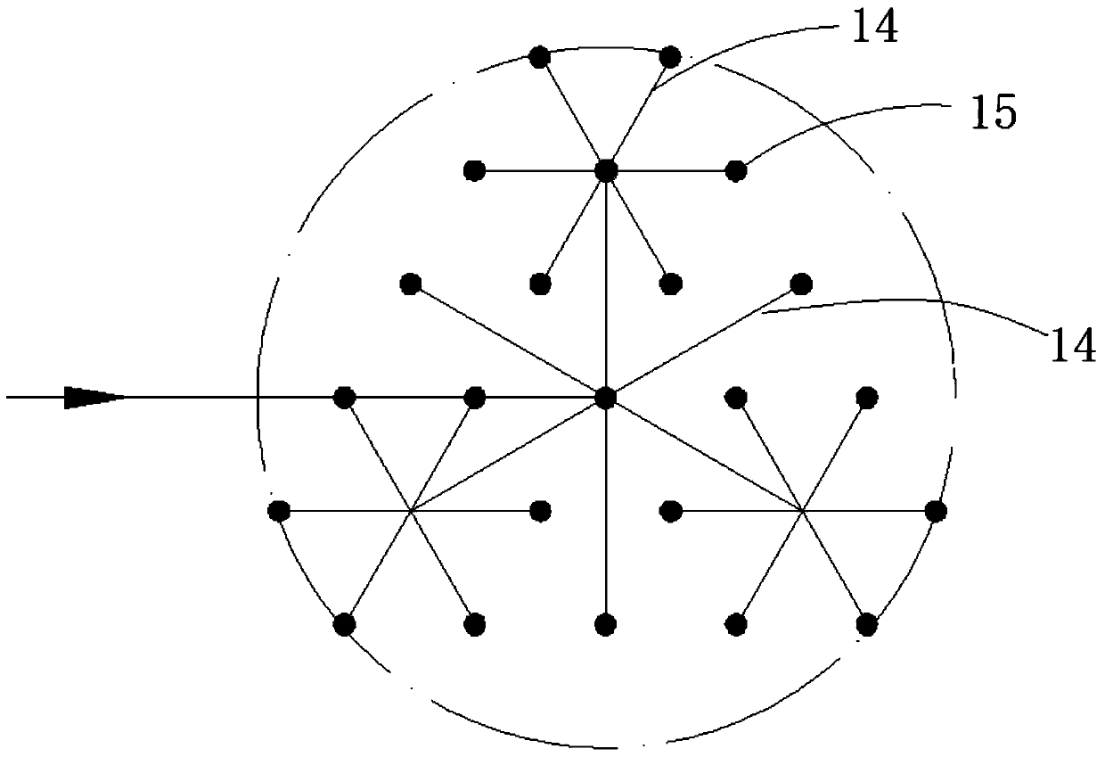
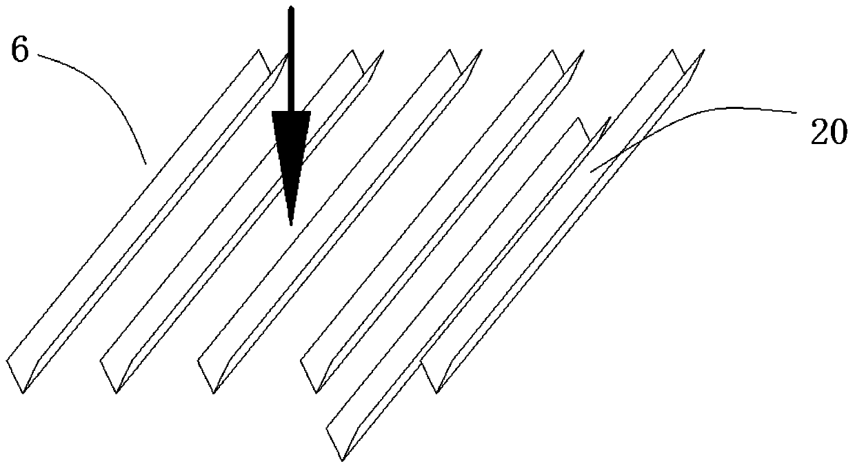
[0032] The spray tower 27 of this embodiment is a wet flue gas spray tower with direct contact between cold and hot zones, which can reduce the temperature of the flue gas and dissolve impurities in the flue gas, such as figure 1 As shown in -4, the spray tower 27 includes a tower body 1, a first group of spray layers 2, a second group of spray layers 3, a first liquid storage tank 4, a second liquid storage tank 5, a turbulent liquid holder 6, The first circulation assembly 7, the second circulation assembly 8 and the cooling assembly.

[0033] In this embodiment, the material of the tower body is Q235 steel plate with a wall thickness of 5 mm, the inner wall of the tower body 1 must undergo anti-corrosion treatment, and the thickness of the anti-corrosion glass flakes is not less than 3 mm.

[0034] The tower body 1 is provided with a first group of spray layers 2 and a second group of spray layers 3, and corresponding to the first group of spray layers 2 for collecting the ...

Embodiment 2

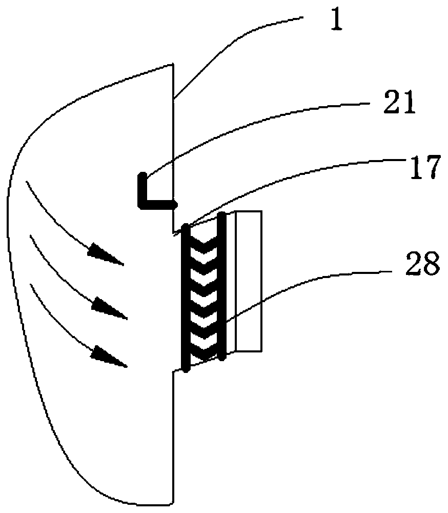
[0049] The exhaust system of this embodiment, such as Figure 5 As shown, it includes a deduster 25, a desulfurizer 26, a spray tower 27 described in Embodiment 1, and a chimney 29 connected in sequence. In order to reduce the humidity of the flue gas discharged, a mist eliminator 28 is set corresponding to the outlet flue 17 of the spray tower 27, and in order to facilitate the setting of the mist eliminator 28, in this embodiment, refer to figure 1 , the demister 28 is arranged on the outside of the spray tower 27 .

[0050] The exhaust system of this embodiment can be used in devices that require flue gas purification and flue gas whitening, such as coal-fired power generation, boiler 22, and the application range of the exhaust system is very wide.

[0051] When the exhaust system is used in the boiler system, it includes a boiler 22, a denitrification device 23, a low-temperature economizer 24, and the above-mentioned exhaust system connected in sequence.


PUM

PropertyMeasurementUnit
Thicknessaaaaaaaaaa

Abstract

The invention relates to the technical field of smoke purification devices, in particular to a spraying tower, an exhaust system and a boiler system. The spraying tower comprises a tower body, a first circulation assembly, a second circulation assembly and a cooling assembly. The tower body is internally provided with a first spraying layer, a second spraying layer, a first liquid storage groove and a second liquid storage groove, wherein the first liquid storage groove corresponds to the first spraying layer and is used for collecting liquid sprayed out through the first spraying layer, the second liquid storage groove corresponds to the second spraying layer and is used for collecting liquid sprayed out through the second spraying layer, and smoke of the tower body sequentially passes through the first spraying layer and the second spraying layer. The first circulation assembly is connected with the first spraying layer and the second liquid storage groove, and the liquid of the second liquid storage groove is conveyed into the first spraying layer. The second circulation assembly is connected with the second spraying layer and the first liquid storage groove, and the liquid in the first liquid storage groove is conveyed into the second spraying layer. The cooling assembly is arranged in the second circulation assembly and cools the liquid in the second circulation assembly.

Description

technical field [0001] The invention relates to the technical field of flue gas purification devices, in particular to a spray tower, an exhaust system and a boiler system. Background technique [0002] Large coal-fired power plants or heating boiler equipment often need to discharge a large amount of flue gas through the chimney during production work. This kind of untreated flue gas is basically in a high-temperature saturated state. During the process of being discharged into the atmosphere, due to the high moisture content of the flue gas and the temperature difference with the air, liquid water will be precipitated during the cooling and mixing process with the air. Easy to form "white plume" or "chimney rain". "White smoke plume" or "chimney rain" seriously affects the visibility of the air, and in the process of falling, it will continuously absorb harmful dust and generate smog, which has a great impact on the environment around the smoke exhaust area. [0003] In ...

Claims


Application Information

Patent Timeline
IPC IPC(8): F28C1/00F28C1/16F28F25/02F28F25/06F23J15/04F23J15/06F25B30/00
CPCF23J15/04F23J15/06F25B30/00F28C1/00F28C1/16F28F25/02F28F25/06F28F2025/005
Inventor 李水清王翔王述浩卓建坤
Owner TSINGHUA UNIV
Why Eureka
Try Eureka