
Liquid level sensor by adopting optical fiber bundle and image processing technology

A liquid level sensor and image processing technology, applied in the field of liquid level sensors, can solve problems such as low precision, mechanical failure, and occupation of capacitive sensors, and achieve the effects of high calculation accuracy, small footprint, and high stability

Inactive Publication Date: 2019-09-20
陕西华腾云物联网有限责任公司
View PDF5 Cites 3 Cited by
  • Summary
  • Abstract
  • Description
  • Claims
  • Application Information

AI Technical Summary

Problems solved by technology

The ultrasonic liquid level sensor is installed outside the storage tank, does not occupy the internal space of the storage tank, and has no live parts inside the storage tank, which is safe, but usually the accuracy is not high, and the measured value is greatly affected by temperature and air pressure
Resistive liquid level sensors can obtain high measurement accuracy, but due to the existence of mechanical devices and moving parts, the real-time performance of measurement is not high, and there is a risk of mechanical failure
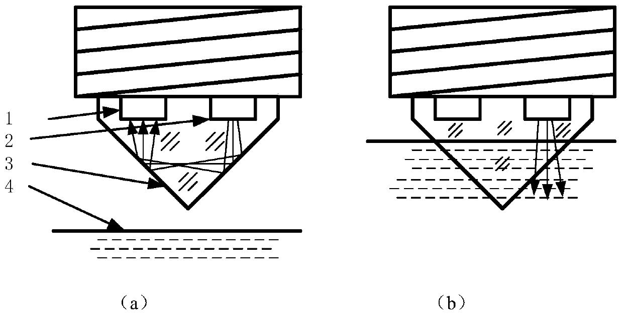
The photoelectric switch type liquid level sensor can only monitor whether the liquid level exceeds a certain fixed position, and cannot give the measured value of the liquid level at any position
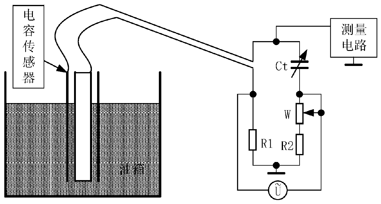
Capacitive liquid level sensors can achieve high measurement sensitivity, but temperature and pressure have a greater impact on the measurement results
In addition, the capacitive sensor occupies the internal volume of the storage tank, and there is a potential safety hazard when the capacitor is charged, and the capacitor and its supporting structure have a large additional weight

Method used


Image

  • Liquid level sensor by adopting optical fiber bundle and image processing technology
  • Liquid level sensor by adopting optical fiber bundle and image processing technology
  • Liquid level sensor by adopting optical fiber bundle and image processing technology

Examples


Embodiment

[0059] Assume that the application conditions are that the maximum depth of the liquid is 1 meter, the measurement resolution is 1 mm, normal temperature and pressure, the wavelength of the light source is 650 nm, and the refractive index of the liquid to the light source is 1.5.

[0060] The number of probes required is 1000. There are 1000 sending and receiving optical fibers each. Arranged in a square matrix of 32X32 at the sending end and receiving end. Choose a plastic optical fiber with an outer diameter of 0.5mm. The section size of the fiber bundle at the illumination end and the image acquisition end is 16X16mm. The section of the detection section is arranged according to 64X32, and the section size is 32X16mm.

[0061] At present, the materials of plastic optical fiber include PS, PMMA, PC, fluoroplastic, etc., and the optical fiber can be selected according to the properties of the liquid.

[0062] Illumination source can choose 1W single red LED, 15 degree angle...


PUM


Abstract

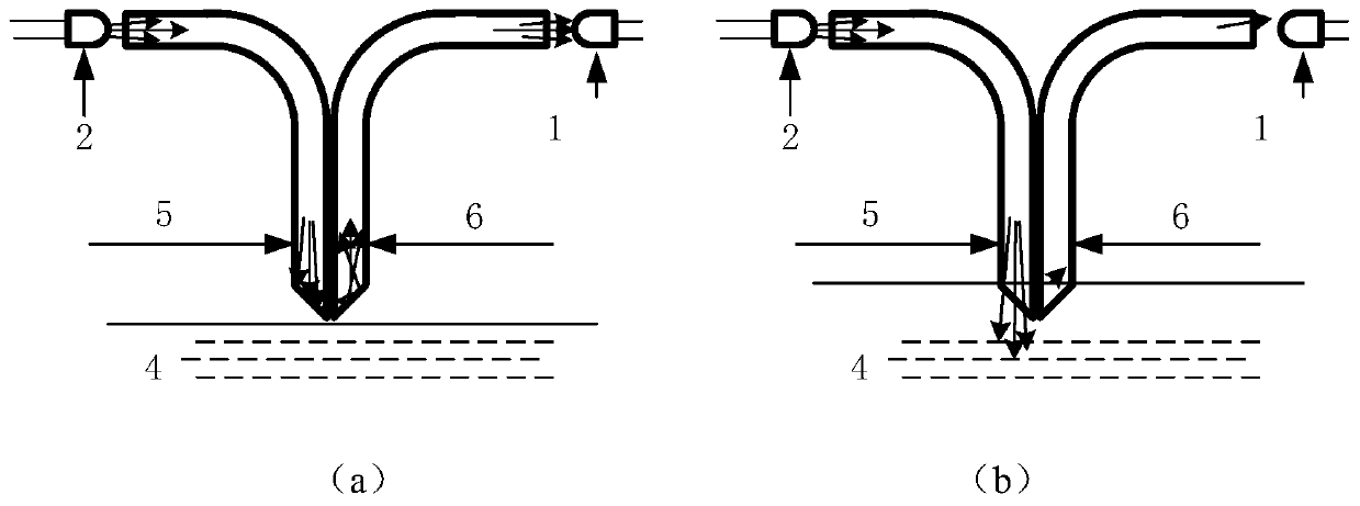
The invention discloses a liquid level sensor by adopting an optical fiber bundle and an image processing technology. The liquid level sensor comprises a light source, an optical fiber bundle and a camera. The light source comprises a light-emitting element; the optical fiber bundle is formed by a plurality of optical fiber probes with different effective degrees, and the effective length refers to the equivalent vertical length of the optical fiber probes; each optical fiber probe is used for representing different liquid level positions and consists of a transmitting optical fiber and a receiving optical fiber, and the transmitting optical fibers and the receiving optical fibers of the optical fiber probes are arranged in parallel and tightly attached together at the detection ends of the optical fiber probes; at the other end of the optical fiber bundle, all the transmitting optical fibers are converged into a bundle, the end face is processed into a plane perpendicular to the optical axis of the optical fibers, and the illuminating light enters all the optical fibers from the end face; all the receiving optical fibers are collected into a bundle, the end face is processed into a plane perpendicular to the optical axis of the optical fibers, and the camera is used for imaging the end face; when the optical fiber probes are in a working state, the other ends, receiving the optical fibers, of the optical fiber probes entering the liquid present low brightness, and the corresponding ends of the optical fiber probes separated from the liquid present high brightness.

Description

technical field [0001] The invention relates to a liquid level sensor using optical fiber bundle and image processing technology, which is mainly used in the field of power machinery using liquid fuel, and can also be used in other fields requiring liquid level measurement. Background technique [0002] All power machinery that uses liquid fuel must use a liquid level sensor to monitor and measure the stock of fuel and other working oils. Currently widely used liquid level sensors include resistive, capacitive, ultrasonic, and photoelectric switch types. Among them, the resistive type should cooperate with the float, and the float is mechanically connected to the potentiometer. The change of the liquid level is transmitted to the potentiometer through the float and related mechanical mechanisms, and becomes the change of the resistance value of the potentiometer. The photoelectric switch liquid level sensor can only detect whether the liquid level reaches a certain position...

Claims


Application Information

Patent Timeline
Patent Type & Authority Applications(China)
IPC IPC(8): G01F23/292
CPCG01F23/292
Inventor 李忠科乐开端杜新虎杨卫军
Owner 陕西华腾云物联网有限责任公司
Learn More