Cladding pumping single-mode terahertz fiber laser

A fiber laser, terahertz technology, applied in the field of terahertz lasers, can solve the problems affecting beam quality, loss, and bulky, and achieve the effects of improving beam quality, improving utilization, and reducing loss

Inactive Publication Date: 2019-09-27
TIANJIN UNIV
View PDF3 Cites 5 Cited by
  • Summary
  • Abstract
  • Description
  • Claims
  • Application Information

AI Technical Summary

Problems solved by technology

Optically pumped terahertz lasers have attracted much attention because of their high output power and long-term stable operation at room temperature. However, their disadvantages are that the equipment is bulky and the energy conversion efficiency of the pump laser is low. Conversion efficiency of optically pumped terahertz lasers crucial
[0003] In recent years, with the development of anti-resonant hollow-core fibers and the proposal of various low-loss terahertz materials, researchers have begun to propose terahertz fiber lasers based on hollow-core fibers, but the end-pumping method is generally used. Due to the lack of high-efficiency mid-infrared / terahertz band splitting devices, the end-pumped terahertz fiber laser still needs to use a small hole coupling input mirror, which leads to the inability of the terahertz resonator to be in an optimal resonance state, which seriously affects the performance of the terahertz laser. Output power and beam quality, and part of the generated terahertz laser will be lost through the small hole at the input end of the pump light
In addition, few studies have considered the single-mode characteristic of THz laser output, which is also an important factor affecting beam quality

Method used


Image

  • Cladding pumping single-mode terahertz fiber laser
  • Cladding pumping single-mode terahertz fiber laser
  • Cladding pumping single-mode terahertz fiber laser

Examples


Embodiment Construction

[0026] The present invention will be described in further detail below in conjunction with the accompanying drawings and specific embodiments. It should be understood that the specific embodiments described here are only used to explain the present invention, not to limit the present invention.

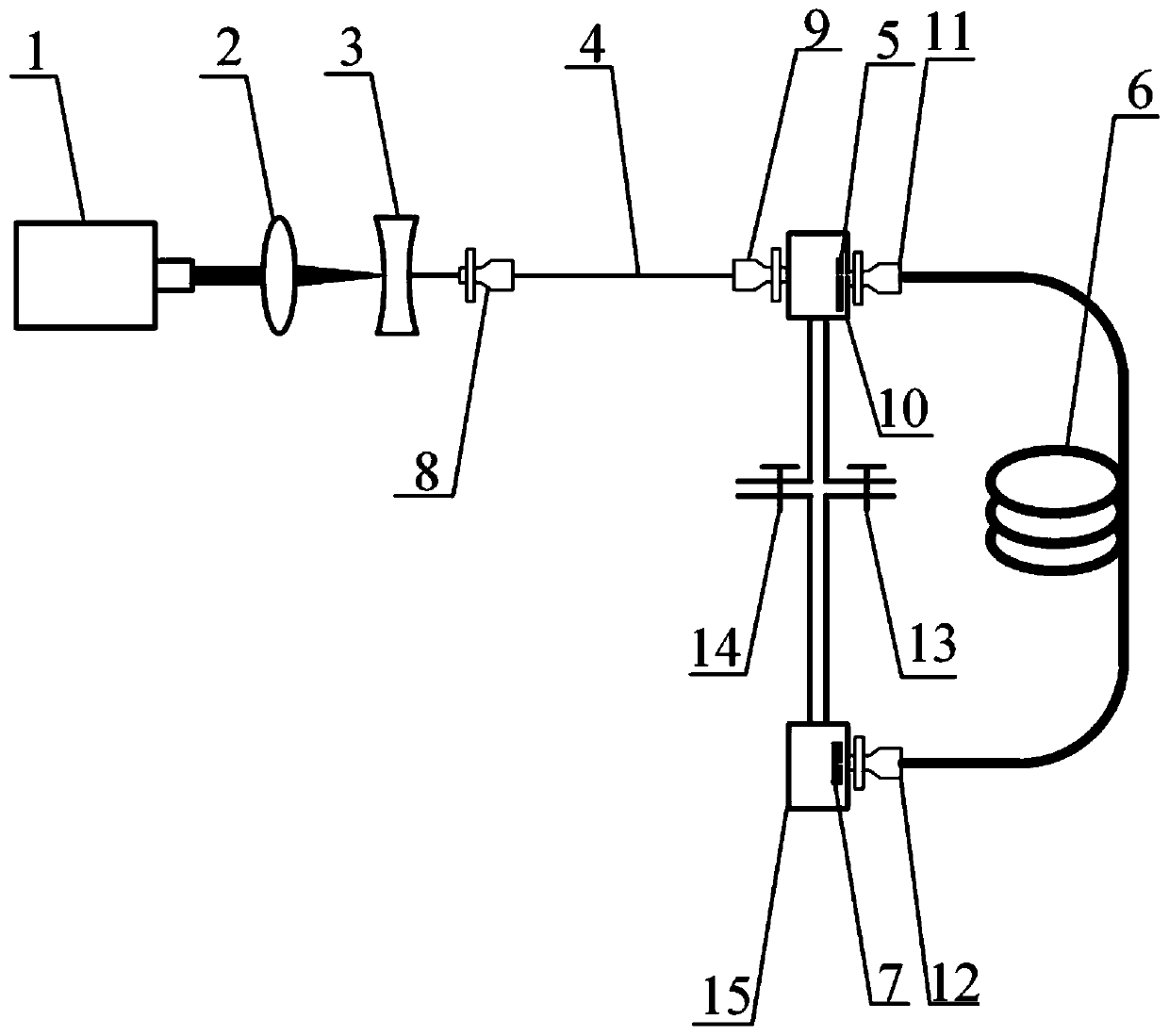
[0027] The cladding-pumped single-mode terahertz fiber laser of this embodiment is as figure 1 As shown, the continuously tunable carbon dioxide laser 1 can output pump laser light with a central wavelength of 9.69 μm. Firstly, use ZnSe convex lens 2 and ZnSe concave lens 3 to control the beam of the pump laser to reduce the spot size of the pump laser so that it can be better coupled with the fiber adapter I8 to enter the mid-infrared hollow core In the middle hollow core region of the optical fiber 4 , the pump light can be transmitted with low loss due to the anti-resonance effect in the mid-infrared hollow core optical fiber 4 . Press the fiber optic adapter II9, fiber optic ada...


PUM

PropertyMeasurementUnit
wavelengthaaaaaaaaaa

Abstract

The invention discloses a cladding pumping single-mode terahertz fiber laser, and the laser comprises a continuous tunable carbon dioxide laser, a zinc selenide convex lens, a zinc selenide concave lens, a mid-infrared hollow-core fiber, a copper-plated reflecting mirror with a centrifugal hole, a composite single-mode terahertz hollow-core fiber and a gold-plated quartz crystal output mirror, which are arranged in sequence; two ends of the mid-infrared hollow-core fiber are respectively connected with a fiber adapter; after the single-mode terahertz hollow-core fiber is connected with the fiber adapter, the two ends of the single-mode terahertz hollow-core fiber are connected with a vacuum air chamber I and a vacuum air chamber II respectively, the copper gold-plated reflecting mirror with the centrifugal holes is packaged in the vacuum air chamber I through a flange, and the gold-plated quartz crystal output mirror is packaged in the vacuum air chamber II through a flange. A vacuumizing system is further connected between the vacuum air chamber I and the vacuum air chamber II, and air pressure control is conducted through the vacuum valve I and the vacuum valve II. The laser overcomes the defects that an ordinary optical pump terahertz laser is large in size and low in light beam quality, and high-power single-mode terahertz output is difficult to achieve.

Description

technical field [0001] The invention relates to the technical field of terahertz lasers, in particular to a cladding-pumped single-mode terahertz fiber laser. Background technique [0002] Terahertz waves refer to electromagnetic waves with a frequency of 0.1-10THz, which have many unique advantages, such as the ability to penetrate non-metallic materials and non-polarized substances, and have extremely low photon energy, so they are widely used in medical imaging and security inspections , environmental monitoring, atmospheric remote sensing, and basic physics research. At present, researchers have developed a variety of terahertz radiation sources, but most of them require harsh working environments or high operating costs. Optically pumped terahertz lasers have attracted much attention because of their high output power and long-term stable operation at room temperature. However, their disadvantages are that the equipment is bulky and the energy conversion efficiency of ...

Claims


Application Information

Patent Timeline
Patent Type & Authority Applications(China)
IPC IPC(8): H01S3/067
CPCH01S3/06708H01S3/06729H01S3/06733
Inventor 史伟张果孙帅盛泉姚建铨
Owner TIANJIN UNIV
Why Eureka
Try Eureka