Gas recovery and concentration device

A gas recovery and concentration device technology, which is applied in gas treatment, combustible gas purification, ion exchange treatment devices, etc., can solve the problems of carbon dioxide recovery rate, insufficient energy saving of concentrated concentration recovery energy, etc., and achieve the effect of improving recovery rate

Active Publication Date: 2019-09-27
SEIBU GIKEN CO LTD
View PDF23 Cites 2 Cited by
  • Summary
  • Abstract
  • Description
  • Claims
  • Application Information

AI Technical Summary

Problems solved by technology

However, it is not sufficient in the recovery rate of carbon dioxide, concentration concentration, and energy saving of recovered energy.

Method used


Image

  • Gas recovery and concentration device
  • Gas recovery and concentration device
  • Gas recovery and concentration device

Examples


Embodiment 1

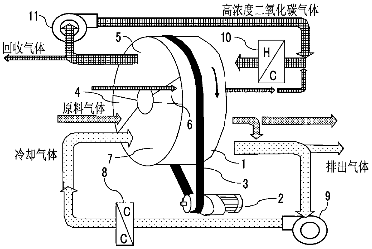
[0112] Figure 4 Example 1 is shown in . With regard to the honeycomb rotor 12, 30 g / m of plastic fibers such as PET fibers containing inorganic fiber bodies such as glass fibers 2 Coating the coating solution mixed with solid amine particles with a particle size distribution of 0.02 to 0.1 mm and a heat-resistant and water-resistant binder on porous paper, and corrugating the dried sheet (photo 2) to a pitch of 3.0 mm and a height of 2.0mm, and it is wound and rotorized to obtain a volume specific gravity of 150kg / m containing 50% by weight of solid amine particles 3 The honeycomb rotor 12. In the present invention, since steam is used to desorb the adsorbed carbon dioxide, it is not necessary to make the honeycomb rotor 12 flame-resistant. However, in order to ensure shape retention and strength in hot water, it is preferable to mix inorganic fibers such as paper glass fibers or PET. Paper made of synthetic fibers such as , etc. is used as a support body, but if it is a n...

Embodiment 2

[0119] Figure 5 Example 2 is shown in . On the front and back of the sheet of aluminum foil 25μ, coat heat-resistant, water-resistant epoxy adhesive, use the sheet that is distributed and bonded with 0.3-1.2mm granular amine-based weak base ion-exchange resin particles ( Figure 14 ) corrugated into a pitch of 9mm and a height of 5.6mm, and further coiled or stacked to obtain a load of 240g / m 3 Carbon dioxide enrichment honeycomb rotor 12 of amine-based weak base ion exchange resin.

[0120] The sheet in which the ion exchange resin is distributed and bonded can be produced, for example, by a method such as Japanese Patent Publication Hei 7-16576, but it is not limited to this method.

[0121] The carbon dioxide recovery and concentration device returns to the adsorption area 13 through the adsorption area 13 and the desorption area 14 along the rotation direction of the honeycomb rotor 12 . When the material gas containing carbon dioxide gas, which is pre-treated to cool ...

Embodiment 3

[0127] Figure 6-a , b, c show the embodiment 3 of the situation where a water curtain purification zone is provided. in addition, Figure 6-b for Figure 6-a The A-A cross-section of the view, Figure 6-c for Figure 6-a The direction view in the B-B section of . For the front and rear boundaries of the adsorption area and the desorption area, the settings are as follows Figure 6-a The advantages of the situation of the water injection curtain raw material gas purification zone 15 and the water injection curtain carbon dioxide purification zone 16 shown in , b and c will be described. At the position where the rotor honeycomb moves from the adsorption area to the desorption area, the raw material gas in the void of the honeycomb is brought into the desorption area to reduce the recovery concentration of carbon dioxide. Moreover, at the position where the rotor honeycomb moves from the desorption area to the adsorption area, the high-concentration carbon dioxide gas in ...


PUM

PropertyMeasurementUnit
particle diameteraaaaaaaaaa

Abstract

The invention relates to a thermal swing type carbon dioxide recovery and concentration device which is a honeycomb rotor recovery and concentration device for recovering carbon dioxide gas from duct gas and the like, that can recover carbon dioxide gas at as high a recovery rate as possible and concentrate to as high a concentration as possible, that can be made smaller, that can use low-temperature heat waste of 100 DEG C or less and reduce the amount of energy for recovery and concentration, and that has high durability. [Solution] A honeycomb rotor carrying adsorption material (solid amines, and the like) particles having adsorption capacity for carbon dioxide gas is rotated in a casing divided and sealed into at least an adsorption zone and a desorption zone and is brought into contact with raw material that includes carbon dioxide in a state where the honeycomb in the adsorption zone is moist so as to adsorb the carbon dioxide gas while carrying out evaporative cooling of water, and then the honeycomb that has adsorbed the carbon dioxide gas is moved to the desorption zone and brought into contact with low pressure vapor so as to desorb high concentration carbon dioxide gas. Thus, it is possible to continuously recover carbon dioxide gas at a high recovery rate and high concentration.

Description

technical field [0001] The invention relates to a temperature swing adsorption carbon dioxide recovery and concentration device, which recovers with a high recovery rate, can be concentrated to a high concentration, can be miniaturized, has high durability, can utilize waste heat below 100° C., and consumes less energy. Background technique [0002] As a response to global warming, the world is trying to reduce carbon dioxide emissions from industry, cars and homes as much as possible. For this reason, efforts are being made to improve energy-consuming equipment into energy-saving equipment and to replace old equipment. In addition, as equipment for generating energy such as power generation, use equipment using renewable energy such as sunlight or wind power, or improve the power generation efficiency of thermal power plants, and develop the recovery of carbon dioxide discharged from thermal power plants in the future. Concentrated to store in the ground or deep sea techno...

Claims


Application Information

Patent Timeline
Patent Type & Authority Applications(China)
IPC IPC(8): B01D53/06B01D53/26B01D53/62B01D53/83B01D53/96B01J20/22B01J20/28B01J20/34C01B32/50
CPCB01D53/06B01J20/22B01J20/26C01B32/50B01J20/28004B01J20/28026B01J20/3466B01J41/12B01D2257/504B01D2259/40056B01D2259/4009B01D2253/311B01D2253/3425B01D2253/206B01D2253/25B01J47/127B01J20/28045Y02P20/129Y02P20/50Y02C20/40B01J49/10B01J41/07B01J47/11B01J49/57B01D53/025B01D53/62B01D53/83B01D53/96B01D2252/204B01D2253/304
Inventor 冈野浩志
Owner SEIBU GIKEN CO LTD
Why Eureka
Try Eureka