Method and equipment for manufacturing continuous sintered magnet

A technology of sintered magnets and manufacturing methods, applied in the direction of inductance/transformer/magnet manufacturing, magnetic objects, magnetic materials, etc., can solve the problems of increasing the production cost of magnetic steel, environmental pollution, and poor static pressure working conditions

Pending Publication Date: 2019-10-11
JIANGXI JLMAG RARE EARTH
View PDF0 Cites 6 Cited by
  • Summary
  • Abstract
  • Description
  • Claims
  • Application Information

AI Technical Summary

Problems solved by technology

The disadvantage of this process is that there are many edges and corners of the green compact during vacuum packaging and transfer, the product is easy to crack, missing corners, and the qualified rate is low; when forming, it needs to be bagged and packaged individually, and the unpacking process is unpacked individually, which is time-consuming and expensive. It is labor-intensive, the processing efficiency is low, and the production cost of the magnetic steel is increased; in addition, the working conditions of the oil-cooled isostatic pressing are poor, and it is easy to cause environmental pollution

Method used


Image

  • Method and equipment for manufacturing continuous sintered magnet
  • Method and equipment for manufacturing continuous sintered magnet
  • Method and equipment for manufacturing continuous sintered magnet

Examples


Embodiment 1

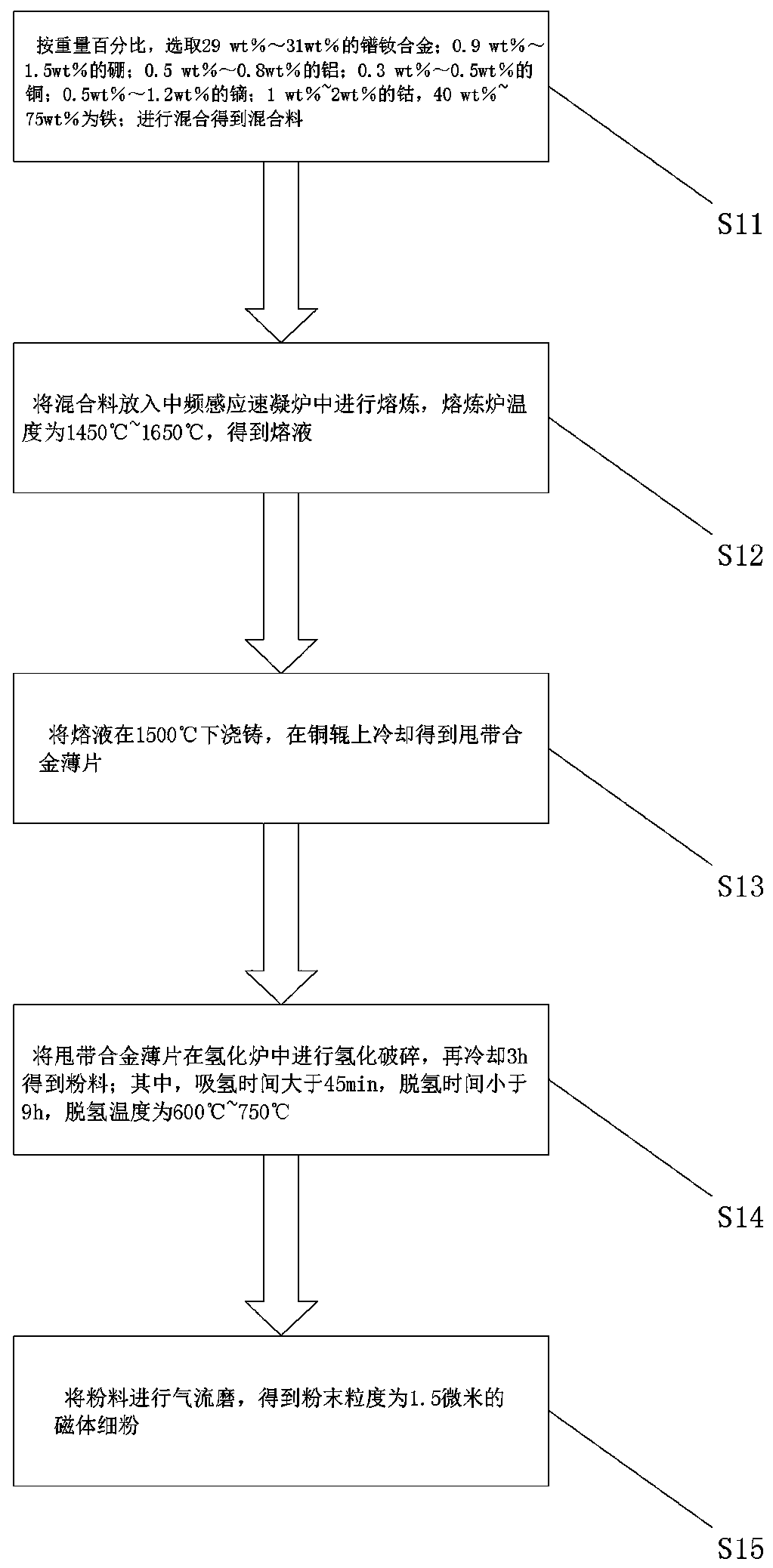
[0059] Step S11, by weight percentage, select 30wt% praseodymium neodymium alloy; 1wt% boron; 0.7wt% aluminum; 0.5wt% copper; 0.8wt% dysprosium; 1wt% cobalt, 66wt% iron; mix get the mixture;

[0060] Step S12, put the mixed material into an intermediate frequency induction quick-setting furnace for melting, and the temperature of the melting furnace is 1600° C. to obtain a melt;

[0061] Step S13, casting the melt at 1500°C, and cooling it on a copper roll to obtain stripped alloy flakes;

[0062] Step S14, carry out hydrogenation crushing of stripped alloy flakes in a hydrogenation furnace, and then cool for 3 hours to obtain powder; wherein, the hydrogen absorption time is 45 minutes, the dehydrogenation time is 9 hours, and the dehydrogenation temperature is 700°C;

[0063] Step S15, jet milling the powder to obtain fine magnet powder with a particle size of 2.5 microns.

[0064] In embodiment one, by weight percentage, select 30wt% praseodymium neodymium alloy; 1wt% boro...

Embodiment 2

[0066] Step S11, by weight percentage, select 29wt% praseodymium neodymium alloy; 1.5wt% boron; 0.8wt% aluminum; 0.5wt% copper; 1.2wt% dysprosium; 2wt% cobalt, 65wt% is iron; mix to obtain a mixture;

[0067] Step S12, putting the mixed material into an intermediate frequency induction quick-setting furnace for melting, and the temperature of the melting furnace is 1500° C. to obtain a melt;

[0068] Step S13, casting the melt at 1500°C, and cooling it on a copper roll to obtain stripped alloy flakes;

[0069] Step S14, carry out hydrogenation crushing of stripped alloy flakes in a hydrogenation furnace, and then cool for 3 hours to obtain powder; wherein, the hydrogen absorption time is 180 minutes, the dehydrogenation time is 8 hours, and the dehydrogenation temperature is 700°C;

[0070] Step S15, jet milling the powder to obtain fine magnet powder with a particle size of 2.5 microns.

[0071] In embodiment two, by weight percentage, choose the praseodymium neodymium allo...

Embodiment 3

[0073] Step S11, by weight percentage, select 29wt% praseodymium neodymium alloy; 0.9wt% boron; 0.5wt% aluminum; 0.3wt% copper; 0.5wt% dysprosium; 1.8wt% cobalt, 67wt% is iron; mixing to obtain a mixture;

[0074] Step S12, putting the mixed material into an intermediate frequency induction quick-setting furnace for melting, and the temperature of the melting furnace is 1500° C. to obtain a melt;

[0075] Step S13, casting the melt at 1500°C, and cooling it on a copper roll to obtain stripped alloy flakes;

[0076] Step S14, carry out hydrogenation crushing of stripped alloy flakes in a hydrogenation furnace, and then cool for 3 hours to obtain powder; wherein, the hydrogen absorption time is 200 minutes, the dehydrogenation time is 7.5 hours, and the dehydrogenation temperature is 720°C;

[0077] Step S15, jet milling the powder to obtain fine magnet powder with a particle size of 2.5 microns.

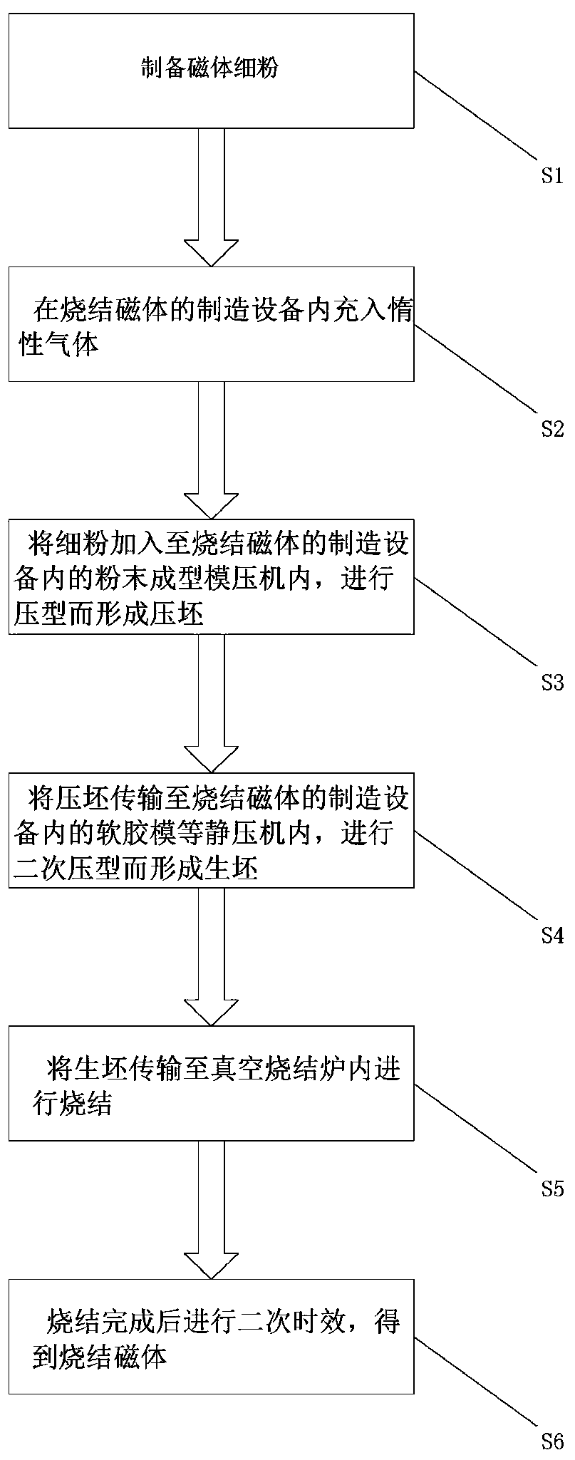
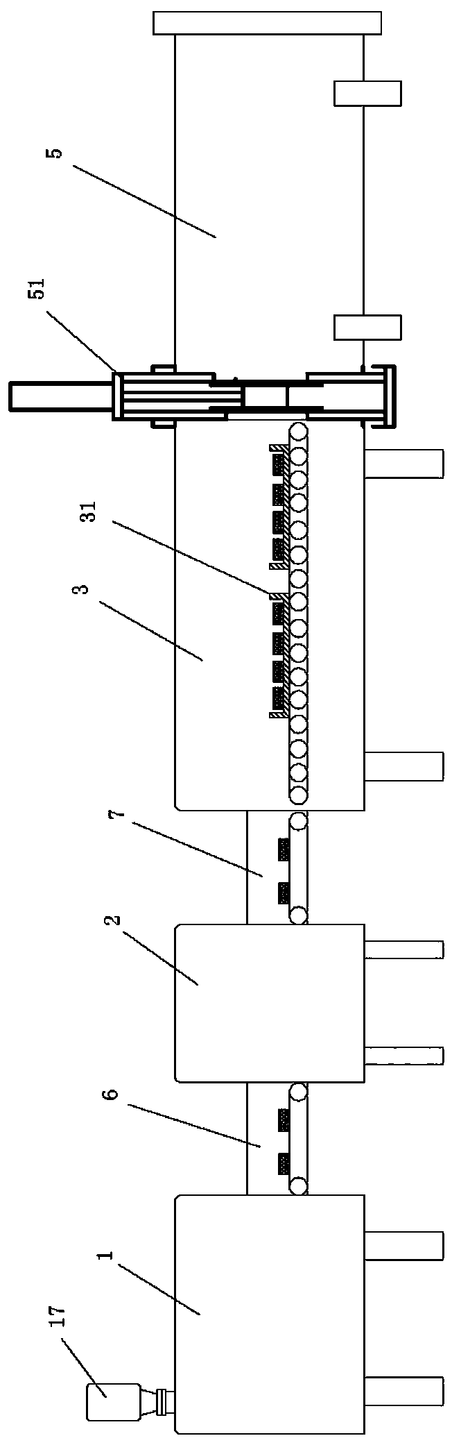
[0078] In the invention, in step S2, the continuous sintered magnet manufacturi...


PUM

PropertyMeasurementUnit
densityaaaaaaaaaa
densityaaaaaaaaaa
particle sizeaaaaaaaaaa

Abstract

The invention relates to the technical field of magnet material production, and relates to a method and equipment for manufacturing a continuous sintered magnet; the preparation method comprises the following steps of firstly, preparing fine powder of the magnet; secondly, filling inert gas into the manufacturing equipment of the continuous sintering magnet; then adding the magnetic fine powder into a powder forming molding press in the manufacturing equipment of the continuous sintering magnet, and performing compression molding to form a pressed blank; then conveying the pressed blank to a soft rubber die isostatic pressing machine in the manufacturing equipment of the continuous sintering magnet, and carrying out secondary compression molding to form a green body; then conveying the green body into a vacuum sintering furnace for sintering; and finally, carrying out secondary aging after sintering is completed, so as to obtain the sintered magnet. According to the method, the inert gas is introduced into the manufacturing equipment of the continuous sintered magnet, under the protection of inert gas, the fine powder of the magnet is subjected to double-time compression, so that after compression molding, the shape is regular, the density is uniform, the orientation degree is good, and then sintering is carried out to prepare the magnet, so that cracking and corner missing arenot formed easily on the magnet, and the percent of pass is ensured.

Description

technical field [0001] The invention relates to the technical field of magnet material production, in particular to a continuous sintered magnet manufacturing method and equipment thereof. Background technique [0002] Rare earth NdFeB permanent magnet material is the third generation of permanent magnet material developed in the early 1980s. Because of its extremely strong magnetism, it is commonly known as the "Permanent Magnet King"; it can attract objects equivalent to 1000 times its own weight, With excellent magnetic characteristics and energy-saving, material-saving and environmental protection effects, it is a high-performance material unmatched by other permanent magnet materials. [0003] As an important functional material, rare earth permanent magnet NdFeB material is also one of the important basic materials supporting the modern electronic information industry; In all aspects of the economy, such as watches, cameras, tape recorders, CD players, VCD players, et...

Claims


Application Information

Patent Timeline
Patent Type & Authority Applications(China)
IPC IPC(8): H01F1/057H01F41/02
CPCH01F1/0577H01F41/0266
Inventor 毛华云金小平周铁夫赖欣
Owner JIANGXI JLMAG RARE EARTH
Why Eureka
Try Eureka