Exhaust cooling capacity utilization system of space liquid hydrogen storage tank
A liquid hydrogen and storage tank technology, applied in the field of space liquid hydrogen storage tank exhaust cooling utilization system, can solve the problems of reducing the liquid hydrogen content of the storage tank, affecting the safe storage of the liquid hydrogen storage tank, and the impact of the safe storage of the storage tank, etc. Achieve the effect of reducing system cooling loss, eliminating environmental heat leakage, and reducing working hours
- Summary
- Abstract
- Description
- Claims
- Application Information
AI Technical Summary
Problems solved by technology
Method used
Image
Examples
Embodiment 1
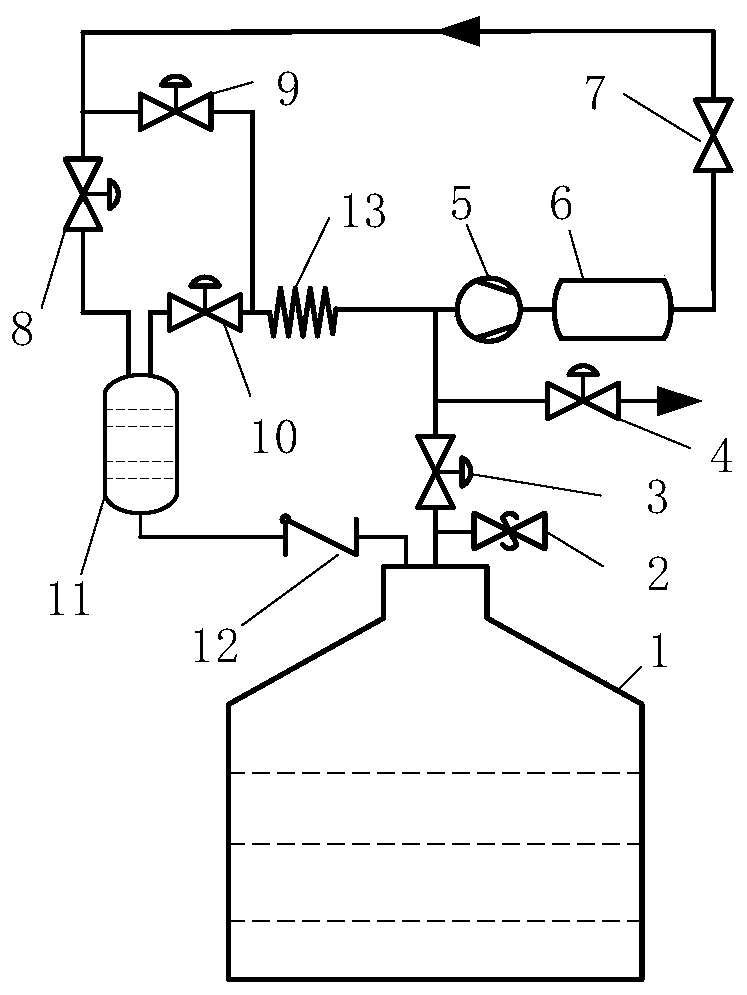
[0028] Such as figure 1 As shown, a space liquid hydrogen storage tank exhaust cooling utilization system includes a liquid hydrogen recovery unit and a cooling transmission unit. The liquid hydrogen recovery unit includes a liquid hydrogen storage tank 1, a diaphragm valve 3, a cryogenic compressor 5, and a buffer tank 6. Throttle valve 7, diaphragm valve 8, gas-liquid separator 11 and check valve 12. The cooling capacity transmission unit includes liquid hydrogen storage tank 1, diaphragm valve 3, cryogenic compressor 5, buffer tank 6, throttling Valve 7, diaphragm valve 8, gas-liquid separator 11, diaphragm valve 10 and evaporator 13;
[0029] The connection relationship between the components of the liquid hydrogen recovery unit and the cooling capacity transmission unit is:
[0030]According to the working medium flow direction of the liquid hydrogen recovery unit, the exhaust pipeline of the liquid hydrogen storage tank 1 is sequentially connected with the inlet of the ...
Embodiment 2
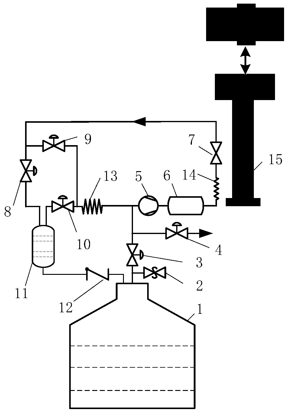
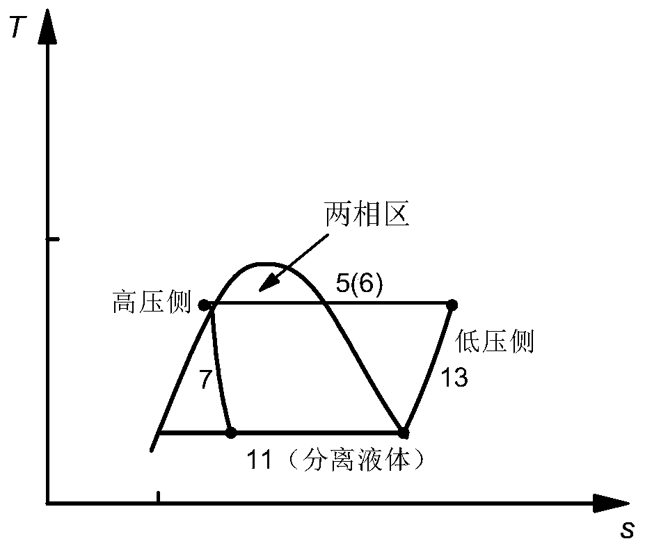
[0037] Such as figure 2 The difference between the exhaust cooling capacity utilization system of a space liquid hydrogen storage tank shown in Example 1 is that the gas hydrogen at the outlet of the evaporator 13 may have problems such as excessive temperature, which may cause the gas hydrogen to be compressed by the cryogenic compressor 5 and buffer tank 6 After the pressure is stabilized, the temperature is throttled at the throttle valve 7, and the cooling capacity is lost. Therefore, a precooling heat exchanger 14 and a precooling mechanism 15 are also provided between the buffer tank 6 outlet and the throttle valve 7 inlet; the buffer tank 6 outlet is connected with the precooling heat exchanger 14, and the precooling heat exchanger 14 Connected to the inlet of the throttle valve 7, the pre-cooling mechanism 15 cools the pre-cooling heat exchanger 14 through a thermal coupling structure, so that the gas-hydrogen temperature drops to the transition temperature (the chara...
PUM
 Abstract
Description
Claims
Application Information
 - R&D
- Intellectual Property
- Life Sciences
- Materials
- Tech Scout
- Unparalleled Data Quality
- Higher Quality Content
- 60% Fewer Hallucinations
Browse by: Latest US Patents, China's latest patents, Technical Efficacy Thesaurus, Application Domain, Technology Topic, Popular Technical Reports.
© 2025 PatSnap. All rights reserved.Legal|Privacy policy|Modern Slavery Act Transparency Statement|Sitemap|About US| Contact US: help@patsnap.com


