Semi-dry desulfurization device and method

A semi-dry desulfurization and desulfurization device technology, applied in the field of flue gas desulfurization, can solve the problems of low desulfurization efficiency, low sliding speed, easy caking of the absorption tower, etc., achieve high desulfurization efficiency and reduce consumption

Active Publication Date: 2019-10-25
FUJIAN LONGKING DSDN ENGINEERING CO LTD
View PDF13 Cites 2 Cited by
  • Summary
  • Abstract
  • Description
  • Claims
  • Application Information

AI Technical Summary

Problems solved by technology

The current mainstream technologies for semi-dry desulfurization towers include: using dry slaked lime powder as a desulfurizer, and using slaked lime slurry as a desulfurizer; among them, the semi-dry desulfurization towers that use dry slaked lime powder as a desulfurizer mainly include CFB desulfurization towers. This kind of desulfurization tower uses water spraying to cool down and increase humidity to create an ion-like reaction environment, and uses the huge sliding speed in the tower to conduct mass transfer and heat transfer, thereby completing desulfurization; but because the water injected cannot remove slaked lime and SO in the flue gas 2 Completely ionized, unable to form a completely ionized reaction environment, the consumption of desulfurizer is large, especially the inlet SO 2 When the concentration is high, the desulfurization agent consumption is greater and the desulfurization efficiency is low; while the semi-dry desulfurization towers using slaked lime slurry as desulfurization agent mainly include SDA desulfurization tower and NID desulfurization tower; among them, the SDA desulfurization tower uses hydrated lime slurry directly sprayed into the tower SO in internal and flue gas 2 Contact, direct ionic reaction, adjust the amount of desulfurizer slurry sp

Method used


Image

  • Semi-dry desulfurization device and method

Examples


Embodiment 1

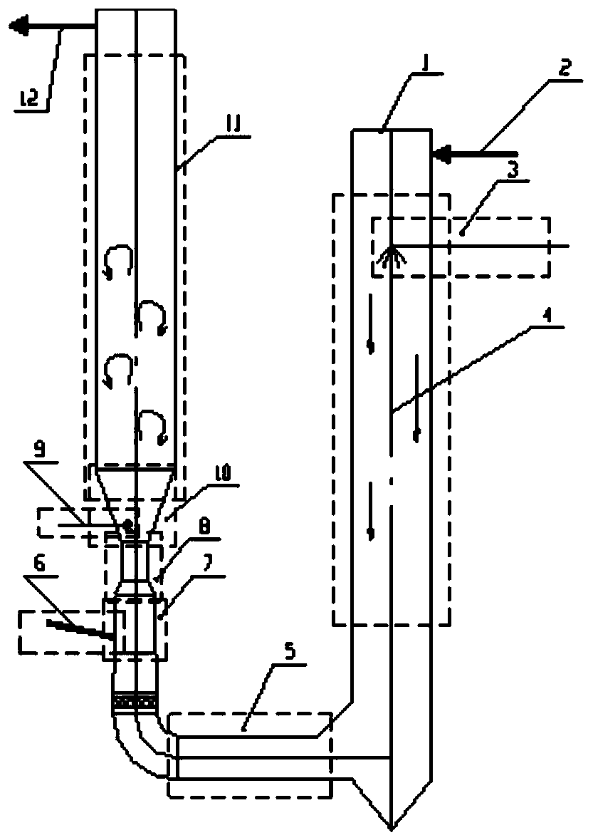
[0075] For the structural schematic diagram of the semi-dry desulfurization device provided in Example 1 of the present invention, see figure 1 As shown, 1 is the casing of the desulfurization device, 2 is the flue gas inlet, 3 is the slurry (lye) spray device, 4 is the semi-dry slurry desulfurization section, 5 is the horizontal flue gas rectification section, and 6 is the Feeding inlet, 7 is the feeding secondary desulfurization section, 8 is the Venturi acceleration section, 9 is the water spray device, 10 is the Venturi outlet section, 11 is the fluidized bed tertiary desulfurization section, and 12 is the desulfurization flue gas outlet.

[0076] The specific working process is as follows:

[0077] (1) The original flue gas enters from the flue gas inlet (2) from the top of the desulfurization device. At the same time, at the top of the desulfurization device, the desulfurization agent slurry passes through the nozzle of the slurry (lye) spray device (3) to be evenly sprayed w...


PUM

PropertyMeasurementUnit
Lengthaaaaaaaaaa

Abstract

The invention provides a semi-dry desulfurization device. The semi-dry desulfurization device comprises a U-shaped desulfurization device shell; the U-shaped desulfurization device shell is sequentially provided with a paste semi-dry first-stage desulfurization section, a horizontal flue gas rectifying section, an adding second-stage desulfurization section, a Venturi acceleration section, a Venturi outlet section and a desulfurization bed third-stage desulfurization section in the flowing direction of flue gas; a flue gas inlet and a spraying device are arranged at the top of the paste semi-dry first-stage desulfurization section; the horizontal flue gas rectifying section is provided with a flue gas rectifying device; the adding second-stage desulfurization section is provided with an adding inlet; the Venturi outlet section is provided with a water spraying device; and the desulfurization bed third-stage desulfurization section is provided with a desulfurization flue gas outlet. Thesemi-dry desulfurization device is adopted for semi-dry desulfurization, an ion-type reaction environment, a high-alkali-to-sulfur-rate reaction environment and a high sliding speed are simultaneously achieved for mass transfer and heat transfer, control can be conducted separately according to the temperature of the flue gas at the inlet and the change of the sulfur capacity, the desulfurizationefficiency is improved, the consumption of a desulfurization agent is decreased, and long-term stable operation is achieved.

Description

Technical field [0001] The invention relates to the technical field of flue gas desulfurization, and more specifically, to a semi-dry desulfurization device and method. Background technique [0002] The semi-dry desulfurization process has the ability to synergistically remove multi-component pollutants, does not produce waste water, does not require anti-corrosion in the system, and the chimney is bright and sensory. It is gradually being used on a large scale. The mainstream technologies of the existing semi-dry desulfurization tower include: using dry slaked lime powder as a desulfurizing agent, and using slaked lime slurry as a desulfurizing agent; among them, the semi-dry desulfurization tower that uses dry slaked lime powder as a desulfurizing agent mainly includes a CFB desulfurization tower. This kind of desulfurization tower uses water spraying to cool and humidify to create a similar ionic reaction environment, and use the huge sliding speed in the tower for mass and he...

Claims


Application Information

Patent Timeline
IPC IPC(8): B01D53/80B01D53/50
CPCB01D53/80B01D53/502B01D53/504B01D2251/304B01D2258/0283B01D2251/402B01D2251/604B01D2251/606
Inventor 陈树发詹威全郭志航朱振炜王建春张哲平邓秀平张原林春源林福林
Owner FUJIAN LONGKING DSDN ENGINEERING CO LTD
Why Eureka
Try Eureka