Method for gasification of fluidized bed gasified fly ash retaining to furnace

A technology of fluidized bed gasification and fly ash, which is applied in the direction of granular/powdered fuel gasification, chemical industry, and the manufacture of combustible gas, etc., which can solve the problems of increasing equipment investment and production costs, and achieve low investment costs for enterprises and high efficiency. The effect of gasification activity and simple process

Inactive Publication Date: 2019-10-25
ANHUI UNIVERSITY OF TECHNOLOGY
View PDF4 Cites 3 Cited by
  • Summary
  • Abstract
  • Description
  • Claims
  • Application Information

AI Technical Summary

Problems solved by technology

However, for fluidized bed gasification enterprises, these methods will increase the equipment investment and production cost of the enterprise, so the best method is to return the gasified fly ash to the fluidized bed gasification furnace for gasification

Method used


Image

  • Method for gasification of fluidized bed gasified fly ash retaining to furnace

Examples


Embodiment 1

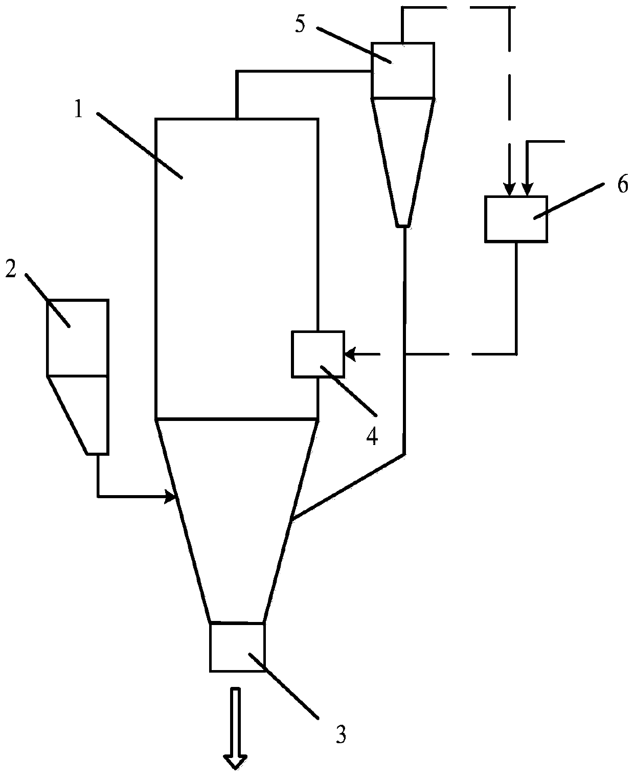
[0015] Example 1: The fluidized bed gasification fly ash is sprayed into the dilute phase zone of the fluidized bed gasification furnace at a temperature of 800-1000° C. with air at a gas velocity of 3-6 m / s, and the gasification pressure is normal pressure. At the same time, the coal material is fed into the gasifier from the bottom of the fly ash injection inlet by the screw feeder, and then falls into the dense phase area, where it undergoes partial combustion and gasification reaction with the air input from the bottom of the gasifier. During the entire gasification process, the carbon conversion rate of raw materials can reach more than 80%.

Embodiment 2

[0016] Example 2: Calcium oxide with a mass fraction of 5% was added to the gasification fly ash as a catalyst and a desulfurizer, the feed oxygen-containing flow was air, and the gasification pressure was normal pressure. At the same time, the coal material is fed into the gasifier from the bottom of the fly ash injection inlet by the screw feeder, and then falls into the dense phase area, where it undergoes partial combustion and gasification reaction with the air input from the bottom of the gasifier. The carbon conversion rate of the raw material can reach more than 85%, and the H in the gas 2 The content of S is greatly reduced.

Embodiment 3

[0017] Example 3: The mixed raw material of fluidized bed gasification fly ash and calcium oxide with a mass fraction of 5% is sprayed into a fluidized bed gasification furnace with a temperature of 800-1000° C. with an oxygen-rich flow with an oxygen content of 30%. In the dilute phase zone, the gasification pressure is normal pressure. At the same time, the coal material is fed into the gasifier from the bottom of the fly ash inlet by the screw feeder, and then falls into the dense phase area, where it is partially burned and gasified with the air input from the bottom of the gasifier. The carbon conversion rate of the raw material can reach more than 90%, and at the same time, the calorific value of the gasification gas can be increased by more than 5%.


PUM


Abstract

The invention discloses a method for gasification of fluidized bed gasified fly ash retaining to a furnace, and belongs to the technical field of comprehensive utilization of coal carbon. According tothe fluidized bed gasification method, firstly, fly ash collected by a gas dust removal system of fluidized bed gasifier is mixed with a catalyst, then the fluidized bed gasified fly ash is transported to the fluidized bed gasifier in a jet flow mode by using an oxygen-containing airflow; a combustion reaction or a gasification reaction of the gasified fly ash occur in a dilute phase area of thefluidized bed gasifier, and gas is produced or heating is provided for the gasification reaction; and at the same time, coal for gasification is transported from the middle lower part of the fluidizedbed gasifier to the gasifier, and partial oxidation and the gasification reaction occur between the coal and a gasification agent in the gasifier. The method can realize furnace retaining gasification of the circulating fluidized bed gasified fly ash, the process is simple, the gasification effect is good, and the problem of utilization of the fly ash of an enterprise is solved.

Description

Technical field: [0001] The invention belongs to the technical field of coal comprehensive utilization, and in particular relates to a method for returning a fluidized-bed gasification fly ash to a furnace for gasification. The method breaks cohesive bituminous coal and is used for fixed-bed gasification. Background technique: [0002] Clean coal conversion is an important way to achieve the overall optimization of resources, energy, and environment, and the sustainable development of the ecological environment. Among them, the fluidized bed gasification technology has the advantages of wide adaptability to coal types, sulfur fixation in the furnace and less nitrogen oxides, and is an important direction for the development of coal conversion technology. The coal gas of fluidized bed gasification technology will contain a large amount of gasification fly ash with high carbon content. The fly ash has small particle size, high degree of graphitization, and poor reactivity, wh...

Claims


Application Information

Patent Timeline
Patent Type & Authority Applications(China)
IPC IPC(8): C10J3/54C10J3/66
CPCC10J3/54C10J3/66Y02P20/10
Inventor 赵志刚吴爽邵如意刘祥春凌强谢瑞伦雷昭崔平
Owner ANHUI UNIVERSITY OF TECHNOLOGY
Why Eureka
Try Eureka