Bone defect repair scaffold, and construction method and preparation method thereof, computer-readable storage medium and equipment

A construction method, bone defect technology, applied in calculation, 3D modeling, image data processing, etc., can solve the problem of porosity and pore shape affecting osseointegration effect, implant and bone elastic modulus mismatch, and lack of fracture healing biology To achieve good controllable pore size, good osseointegration effect, and favorable healing effect

Pending Publication Date: 2019-11-05
SHANGHAI NINTH PEOPLES HOSPITAL AFFILIATED TO SHANGHAI JIAO TONG UNIV SCHOOL OF MEDICINE
View PDF5 Cites 6 Cited by
  • Summary
  • Abstract
  • Description
  • Claims
  • Application Information

AI Technical Summary

Problems solved by technology

[0004] At present, the artificial bone substitutes used clinically for bone defect repair mainly have the following problems: 1) The elastic modulus of the implant does not match that of the bone, and stress shielding is likely to occur after implantation, which accelerates the loss of bone mass and the risk of secondary fractures Increase; 2) The implant does not have the biological f...

Method used


Image

  • Bone defect repair scaffold, and construction method and preparation method thereof, computer-readable storage medium and equipment
  • Bone defect repair scaffold, and construction method and preparation method thereof, computer-readable storage medium and equipment
  • Bone defect repair scaffold, and construction method and preparation method thereof, computer-readable storage medium and equipment

Examples


preparation example Construction

[0060] The third aspect of the present invention provides a preparation method of the bone defect repair scaffold described above, the preparation method comprising: constructing a bone defect repair scaffold model according to the construction method of the above bone defect repair scaffold model, and preparing a bone defect repair scaffold.

[0061] According to the reverse modeling of the patient's imaging (CT data and / or MRI data), a computer STL file is generated, and then the file is transferred to the program of the 3D printer to start printing. Printing process: Print layer by layer from bottom to top according to the STL file. The printing material is tantalum metal powder or tantalum alloy powder, and the whole process is carried out in an argon environment. First, a layer of tantalum metal powder or tantalum alloy powder is laid on the printed substrate, and then the laser print head of the printer emits a high-energy laser to melt the tantalum metal powder or tanta...

Embodiment 1

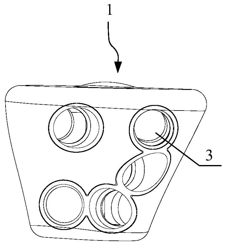
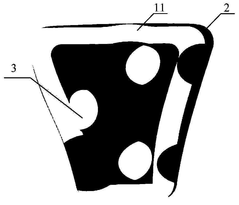
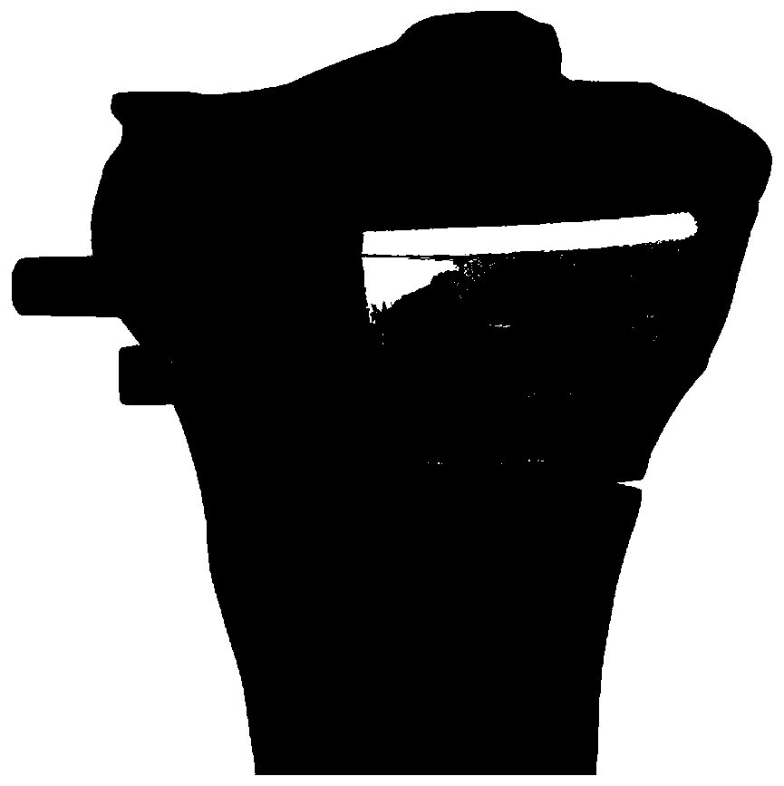
[0070] A bone defect repair bracket, comprising a bone defect repair bracket body 1 and a fusion surface layer 2, the fusion surface layer 2 is provided on the contact surface between the bone defect repair bracket body 1 and the bone, and the bone defect repair bracket body 1 has a hollow cavity 11, the fusion surface layer 2 is a porous structure, and the bone defect repair bracket is made of tantalum metal. The volume ratio of the hollow lumen 11 to the bone defect repair scaffold is 6:10. The shape of the bone defect repair bracket is the shape of the patient's bone defect. The porous structure is a layered structure of several layers, each layer of the layered structure has a plurality of micropores, and the micropores of the layers communicate with each other. The thickness of the fusion surface layer is 3.5 mm, the pore diameter of the fusion surface layer is 800 μm, and the porosity of the fusion surface layer is 70%. The bone defect repair bracket is provided with s...


PUM

PropertyMeasurementUnit
Thicknessaaaaaaaaaa
Apertureaaaaaaaaaa
Apertureaaaaaaaaaa

Abstract

The invention provides a bone defect repair scaffold, and a construction method and a preparation method thereof, a computer-readable storage medium and equipment. The bone defect repair scaffold includes a bone defect repair scaffold body and a fusion surface layer. The contact surface between the bone defect repair scaffold body and a bone substance is provided with the fusion surface layer. Thebone defect repair scaffold body has a hollow inner cavity, the fusion surface layer is of a porous structure, and the bone defect repair scaffold is made of tantalum metal or tantalum alloy. The bone defect repair scaffold effectively avoids the stress shielding effect and reduces the risk of secondary fracture; tantalum metal or tantalum alloy is a biophilic metal, has no toxic or side effectson a human body, has excellent endophytic biological properties and has the function of promoting the bone defect repair; the porous structure of the tantalum metal or tantalum alloy is conducive to growth of newly regenerated bones into the material and good osseointegration effect is obtained.

Description

technical field [0001] The invention belongs to the technical field of bone repair, and in particular relates to a bone defect repair bracket, a construction method, a preparation method, a computer-readable storage medium, and a device. Background technique [0002] Bone defect is a common clinical disease. Various congenital diseases such as infection, tumor, trauma, surgical debridement after osteomyelitis are the main causes of bone defect. Depending on the size of the bone defect, the stability of the bone will be affected to varying degrees. The bone that has lost its stability is significantly less resistant to external impacts, so secondary fractures may occur under the action of a slight external force. In addition, due to the loss of part of the bone, the patient's fracture healing, bed rest and immobilization time will be significantly prolonged, which will bring a series of complications. In order to restore the stability of the bone and avoid secondary fracture...

Claims


Application Information

Patent Timeline
IPC IPC(8): A61L27/56A61L27/50A61L27/04G06T17/00B22F3/11B22F5/00B33Y50/00B33Y10/00B33Y80/00
CPCA61L27/56A61L27/50A61L27/04G06T17/00B22F3/11B22F5/00B33Y50/00B33Y10/00B33Y80/00A61L2430/02G06T2207/30008
Inventor 郝永强郭煜沈陆姜闻博
Owner SHANGHAI NINTH PEOPLES HOSPITAL AFFILIATED TO SHANGHAI JIAO TONG UNIV SCHOOL OF MEDICINE
Why Eureka
Try Eureka