Laser cleaning-texturing composite machining head

A technology of laser cleaning and compound processing, which is applied in the laser field, can solve problems such as high operating cost, low processing efficiency, and poor surface quality, and achieve the effects of increasing laser absorption rate, improving efficiency, and shortening time intervals

Active Publication Date: 2019-11-08
HARBIN INST OF TECH
View PDF7 Cites 2 Cited by
  • Summary
  • Abstract
  • Description
  • Claims
  • Application Information

AI Technical Summary

Problems solved by technology

[0004] The present invention aims to solve the problem of poor surface quality and low processing efficiency of materials (aluminum and its alloys, titanium and its alloys, high-strength steel, etc.) that require laser texturing after laser cleaning or that require laser cleaning before laser texturing. and high operating costs

Method used


Image

  • Laser cleaning-texturing composite machining head
  • Laser cleaning-texturing composite machining head
  • Laser cleaning-texturing composite machining head

Examples


specific Embodiment approach 1

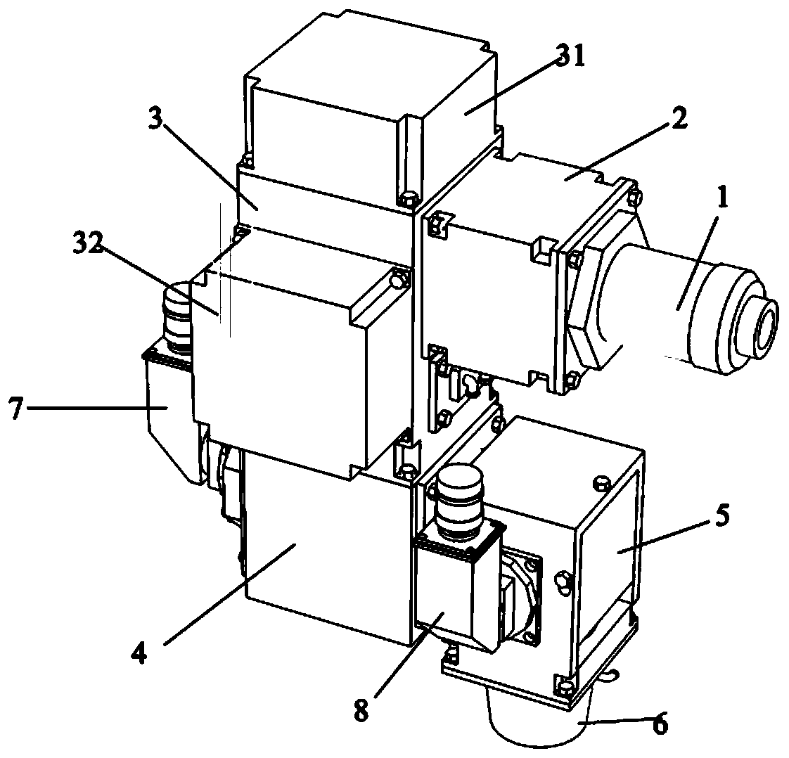
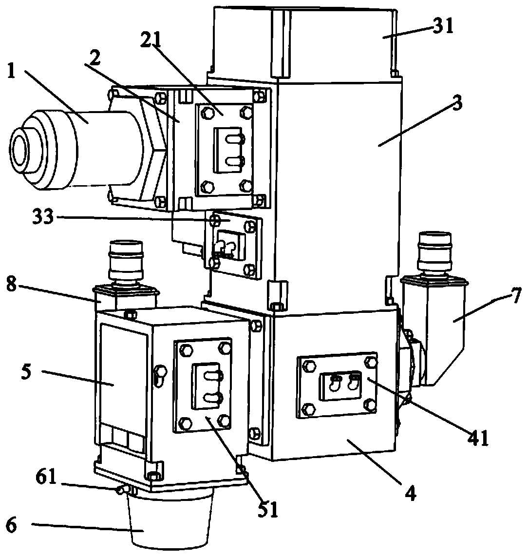
[0024] Specific implementation mode one: combine Figures 1 to 4 Describe this embodiment, a laser cleaning-texturing composite processing head of this embodiment, which includes a laser interface 1, a collimating mirror assembly 2, a vibrating mirror assembly 3, a reflecting mirror assembly 4, a spectroscopic focusing mirror assembly 5, a dust removal and adsorption Component 6, CCD camera component one 7 and CCD camera component two 8;

[0025] One end of the laser interface 1 is connected to the laser, and the other end is connected to the collimating mirror assembly 2; the collimating mirror assembly 2 is connected to the vibrating mirror assembly 3; The rear end of the focusing mirror assembly 5 is connected, and the bottom of the spectroscopic focusing mirror assembly 5 is connected with the dust removal and adsorption assembly 6; the CCD camera assembly one 7 is arranged on the rear part of the spectroscopic focusing mirror assembly 5, and the CCD camera assembly two 8 ...

specific Embodiment approach 2

[0031] Specific implementation mode two: combination Figures 1 to 4Describe this embodiment, the difference between this embodiment and specific embodiment 1 is: the cleaning laser power is 100-500W, and the moving speed of the light spot is 100-3000mm / min; the textured laser power is 300-1000W, and the moving speed of the light spot is 100-3000mm / min; the total power of the laser beam is 400-1500W.

[0032] Other compositions and connection methods are the same as those in Embodiment 1.

specific Embodiment approach 3

[0033] Specific implementation mode three: combination Figures 1 to 4 Describe this embodiment, the difference between this embodiment and specific embodiment 1 is: the cleaning laser power is 300-500W, and the moving speed of the spot is 500-3000mm / min; the texturing laser power is 500-1000W, and the moving speed of the spot is 500-3000mm / min; the total power of the laser beam is 1000-1500W.

[0034] Other compositions and connection methods are the same as those in Embodiment 1.


PUM

PropertyMeasurementUnit
surface roughnessaaaaaaaaaa

Abstract

The invention discloses a laser cleaning-texturing composite machining head and relates to the field of laser. The laser cleaning-texturing composite machining head aims to solve the problems that after laser cleaning, laser texturing machining needs to be performed or before laser texturing, laser cleaning machining needs to be performed, a manufactured material is poor in surface quality, the machining efficiency is low, and the running cost is high. The laser cleaning-texturing composite machining head comprises a laser interface, a collimating mirror assembly, a galvanometer assembly, a reflecting mirror assembly, a light splitting focusing lens assembly, a dust removing adsorbing assembly, a first CCD camera assembly and a second CCD camera assembly. A light splitting focusing deviceis designed in the laser cleaning-texturing composite machining head, the advantages of laser cleaning and laser texturing are played, and the purposes of simplifying the process, saving cost, savingtime, improving efficiency, and improving the cleaning and texturing quality are achieved. The laser cleaning-texturing composite machining head is applied in the laser machining field.

Description

technical field [0001] The invention relates to the field of lasers, in particular to a laser cleaning-texturing composite processing head. Background technique [0002] Laser cleaning technology was proposed in 1965. After nearly 50 years of development, it has been used in many fields such as microelectronics, construction, nuclear power plants, aerospace, marine ships, automobile manufacturing, medical treatment, and cultural relics protection. Laser cleaning has the advantages of green, good cleaning effect, wide application range, easy automatic control, high precision, etc. It is known as the green cleaning technology with the most development potential in the 21st century. Based on these outstanding advantages, laser cleaning is in sharp contrast with chemical cleaning, ultrasonic cleaning and mechanical cleaning, and is expected to partially or completely replace traditional cleaning methods in the future. At the same time, laser texturing technology (LTT), as a tex...

Claims


Application Information

Patent Timeline
Patent Type & Authority Applications(China)
IPC IPC(8): B08B7/00B23K26/352
CPCB08B7/0042B23K26/352
Inventor 彭睿雷正龙田泽孙浩然黎炳蔚
Owner HARBIN INST OF TECH
Why Eureka
Try Eureka