
A PLL Based on Preset Frequency and Dynamic Loop Bandwidth

A preset frequency and phase-locked loop technology, applied in the automatic control of power, electrical components, etc., can solve the problems affecting the overall power consumption and occupation of the chip, and achieve the effect of eliminating noise and high resolution

Active Publication Date: 2020-12-08
BEIJING INSTITUTE OF TECHNOLOGYGY
View PDF10 Cites 0 Cited by
  • Summary
  • Abstract
  • Description
  • Claims
  • Application Information

AI Technical Summary

Problems solved by technology

[0004] In the transceiver chip, the length of time for the phase-locked loop to establish a steady state process directly determines the working time of the entire loop, thus affecting the overall power consumption of the chip
In addition, the voltage-controlled oscillator in the phase-locked loop occupies a large part of the overall power consumption of the phase-locked loop

Method used


Image

  • A PLL Based on Preset Frequency and Dynamic Loop Bandwidth
  • A PLL Based on Preset Frequency and Dynamic Loop Bandwidth
  • A PLL Based on Preset Frequency and Dynamic Loop Bandwidth

Examples


Embodiment 1

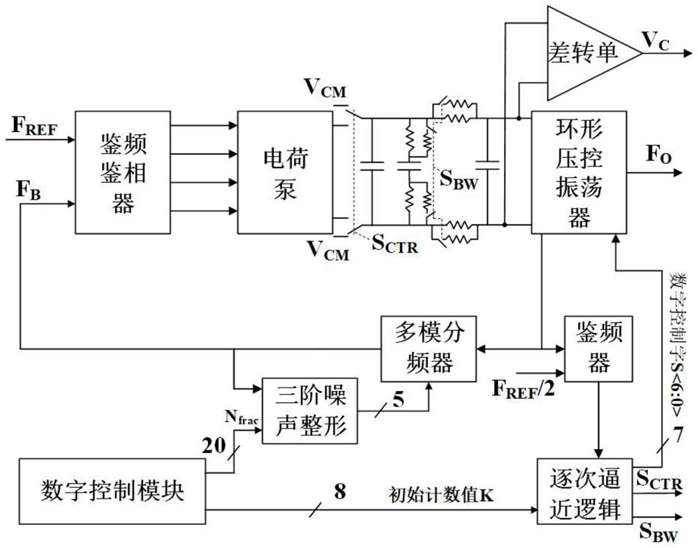
[0057] A phase-locked loop based on a preset frequency and a dynamic loop bandwidth can be applied to a fast output frequency locking circuit to reduce the overall overall power consumption of the circuit.

[0058] The block diagram of the present invention is as figure 1 As shown, the fast locking of the phase-locked loop is realized based on the preset frequency and dynamic loop bandwidth technology, which mainly includes a fully differential frequency detector PFD, a fully differential charge pump CP, a ring voltage controlled oscillator Ring VCO, a multi-mode Frequency divider MMD and low pass filter LPF.

[0059] The frequency and phase detector PFD is a fully differential structure, called a fully differential frequency and phase detector, which is implemented by static CMOS to reduce the overall power consumption of the system;

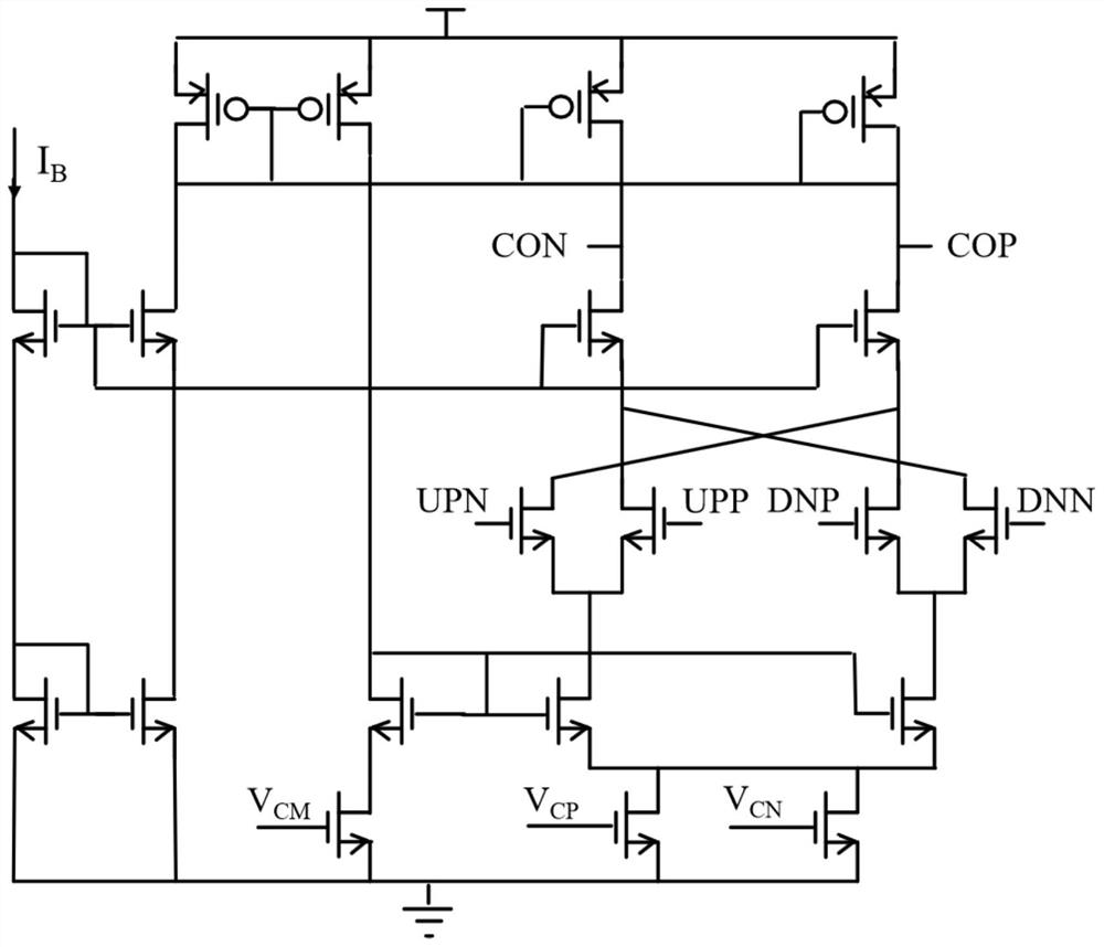
[0060] Among them, the charge pump CP is implemented with a fully differential static CMOS structure, which is called a fully differential ch...

Embodiment 2

[0090] The phase-locked loop establishment process described in this application is made up of frequency tracking and phase locking, first realizes frequency locking and then realizes phase locking, and its total establishment time is as formula (1)

[0091]

[0092] where BW is the loop bandwidth of the PLL.

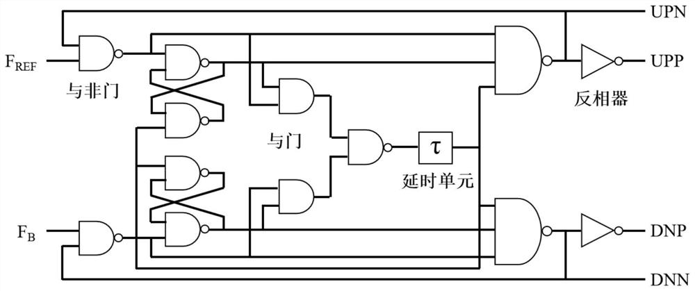
[0093] The structure of the phase frequency detector PFD is as follows figure 2 shown. The combinational logic circuit composed of NAND gate and D flip-flop will instantaneously compare the reference frequency F REF and feedback frequency F B phase to realize the function of charging and discharging. At the same time, in order to eliminate the dead zone characteristics of the charge pump and the noise caused by the dynamic current mismatch of the charge pump, a delay link is introduced to eliminate it, so as to ensure that the value of the delay link is the smallest when the charge pump is fully turned on, and a higher operating efficiency can be obtained. frequ...


PUM


Abstract

The invention relates to a phase-locked loop based on preset frequency and dynamic loop bandwidth, and belongs to the technical field of phase-locked loops under radio frequency circuits. The circuitcomprises a phase frequency detector, a charge pump, an LPF, a differential-to-single operational amplifier, a multi-mode frequency divider, a frequency locking ring, a third-order noise shaping module and a digital control module. The phase frequency detector and the charge pump are of a fully differential structure. The LPF adopts a third-order filter capacitor; the multi-mode frequency divideris formed by cascading a plurality of 2 / 3 frequency dividers, wherein the phase frequency detector is connected with the charge pump, the charge pump is connected with the voltage-controlled oscillator, the LPF is connected between the charge pump and the annular voltage-controlled oscillator, the annular voltage-controlled oscillator is connected with the multi-mode frequency divider, and the multi-mode frequency divider is simultaneously connected with the third-order noise shaping circuit and the phase frequency detector. The phase-locked loop can realize output frequency locking in an extremely short time, is suitable for occasions requiring rapid locking during frequent power-on and power-off, and ensures relatively high resolution; the third-order noise shaping circuit moves noise toa high frequency band, and noise suppression is realized through LPF.

Description

technical field [0001] The invention relates to a phase-locked loop based on preset frequency and dynamic loop bandwidth, and belongs to the technical field of phase-locked loops under radio frequency circuits. Background technique [0002] In modern communication systems, the operating frequency of most circuits is above 100MHz, while traditional crystal oscillators are limited by their own materials and technical problems, and can only generate signals of tens of megahertz, which cannot meet the needs of working circuits. In order to solve this problem, engineers adopt a closed-loop control method to generate stable frequency multiplied signals for circuit use through phase-locked loop PLL technology. The emergence of phase-locked loop technology has made wireless technology develop rapidly and has become an indispensable cornerstone of modern communication circuits. [0003] Biomedical transceiver chips need to be used for a long time at a lower power supply voltage, so ...

Claims


Application Information

Patent Timeline
Patent Type & Authority Patents(China)
IPC IPC(8): H03L7/087H03L7/099H03L7/18
CPCH03L7/087H03L7/0995H03L7/18
Inventor 周波李尧金烨然刘宇杰
Owner BEIJING INSTITUTE OF TECHNOLOGYGY
Learn More