High-temperature dust removal and denitration integrated purifying ceramic filter element flange and preparation technology thereof

A ceramic filter element and technology of preparation process, applied in flange connection, chemical instruments and methods, filtration and separation, etc., to achieve the effects of excellent tensile strength, production cost saving, and high dimensional accuracy

Inactive Publication Date: 2019-11-19
JIANGXI BOCENT TEC CO LTD
View PDF3 Cites 1 Cited by
  • Summary
  • Abstract
  • Description
  • Claims
  • Application Information

AI Technical Summary

Problems solved by technology

[0004] Aiming at the many problems existing in the installation and use of the current ceramic filter element and the shortcomings of the existing flange processing and manufacturing process, the present invention provides a flange for a high-temperature dust-nitrification integrated ceramic filter element and its preparation process. The flange of the ceramic filter element is resistant to high temperature, corrosion resistance, high strength, and the processing technology is simple. The material selection for flange processing is cheap and easy to obtain, which facilitates the installation and use of the ceramic filter element to the greatest extent, and saves production costs.

Method used


Image

  • High-temperature dust removal and denitration integrated purifying ceramic filter element flange and preparation technology thereof
  • High-temperature dust removal and denitration integrated purifying ceramic filter element flange and preparation technology thereof
  • High-temperature dust removal and denitration integrated purifying ceramic filter element flange and preparation technology thereof

Examples


Embodiment 1

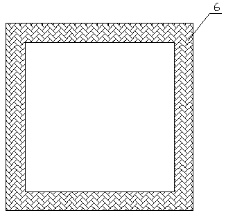
[0026] a. Form and sinter the ceramic powder with the same formulation as the ceramic filter element to make a square frame-shaped integral structure 6 with a thickness of 20mm and a height of 50mm (such as figure 1 shown), the inner diameter of the structural part should be slightly larger than the outer diameter of the square ceramic filter element 1, and the gap between the two should be controlled at 1.5mm;

[0027] b. Use a hardener to surface-treat the bonded interface parts of the filter element and the overall structural part;

[0028] c. Use the glue injection process to fill the high temperature refractory cement between the ceramic filter element and the structural parts. The amount of cement is based on fully filling the gap between the structural parts and the filter element;

[0029] d. The binder is naturally dried at room temperature for 12 hours, and then transferred to a drying oven at 200°C for 12 hours to ensure that the binder is fully cured, thereby makin...

Embodiment 2

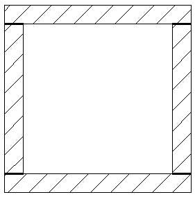
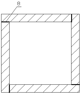
[0033] a. Process the ceramic fiberboard into a box-shaped combined structural part II7 with a thickness of 20mm and a height of 50mm and an adhesive layer 8 (such as figure 2 or image 3 shown), and the integral structural part 6 of the same size is superimposed on the combined structural part II to form a two-layer structural part; the gap between the inner surface of the two-layer structural part and the outer surface of the ceramic filter element is controlled at 3 mm.

[0034] b. Use a hardener to surface-treat the bonding surface of the filter element and the two-layer structure;

[0035] c. Use the glue coating process to brush high-temperature refractory cement on the outer surface of the ceramic filter element and the inner surface of the two-layer structural parts, assemble the ceramic filter element and the two-layer structural parts together, and scrape off the excess cement with a scraper;

[0036] d. The binder is naturally dried at room temperature for 4 hours...

Embodiment 3

[0039] a. Process the ceramic fiber felt into a square frame-shaped combined structural member I5 with a thickness of 25mm and a height of 20mm and an adhesive layer 8 (such as figure 2 or image 3 shown); and the above-mentioned two-layer structure of the same size is superimposed on the composite structure I to form a three-layer structure (such as Figure 4 and Figure 5 shown), the gap between the inner surface of the three-layer structure and the outer surface of the ceramic filter element is controlled at 5mm.

[0040] b. Use a hardener to treat the surface of the bonding interface between the ceramic filter element and the three-layer structure;

[0041] c. Select the ceramic powder and aluminum phosphate glue with the same formula as the ceramic filter element to mix at a ratio of 2:1 to prepare a high-temperature resistant adhesive, and use the glue injection process to fill the self-made high-temperature resistant adhesive between the filter element and the three-...


PUM

PropertyMeasurementUnit
porosityaaaaaaaaaa
thicknessaaaaaaaaaa

Abstract

The invention discloses a high-temperature dust removal and denitration integrated purifying ceramic filter element flange and a preparation technology thereof. The flange is composed of one or a combination containing more than one of an integral structural member, a combined structural member I and a combined structural member II, the integral structural member is used as a flange, or the integral structural member is combined with one or two of the combined structural member I and the combined structural member to serve as the flange, a ceramic is filled with an inorganic high-temperature adhesive by applying a glue in order to prepare the ceramic filter element flange; and the ceramic filter element and the flange are integrally covered with a high temperature-resistant fiber cloth, sothe obtained flange has the advantages of good high temperature resistance, good corrosion resistance and stable chemical properties. A ceramic module and the high temperature adhesive have a certainbuffering ability at a high temperature, or have a thermal expansion coefficient close to that of the ceramic filter element, so the flange can withstand a large degree of thermal expansion and contraction without damaging the ceramic filter element.

Description

technical field [0001] The invention belongs to the technical field of ceramic filter elements, and in particular relates to a flange of a high-temperature dust-nitration integrated ceramic filter element and a preparation process thereof. Background technique [0002] Industries such as metallurgy, building materials, electric power and coal chemical industry produce a large amount of high-temperature flue gas every year. The flue gas has a high dust content and is easy to adhere to. The high-temperature section of the flue gas contains a large amount of high-grade waste heat. To meet the requirements of environmental protection emission standards, these high-temperature dust-laden flue gases must be treated. The high-temperature dust-nitrification integrated ceramic filter element has a large number of fine pore structures, large specific surface area, high temperature resistance, corrosion resistance, high mechanical strength and stable structure and is not easily deforme...

Claims


Application Information

Patent Timeline
Patent Type & Authority Applications(China)
IPC IPC(8): B01D39/20B01D46/00B01D46/24B01D46/42B01D53/86B01D53/60B01D53/56B01D53/48F16L23/00C04B37/02
CPCB01D39/2068B01D46/0001B01D46/2418B01D46/2448B01D46/4272B01D53/8603B01D53/8631B01D53/8637B01D2239/04B01D2239/10C04B37/023F16L23/00
Inventor 徐鹏吴汉阳
Owner JIANGXI BOCENT TEC CO LTD
Why Eureka
Try Eureka