Steam refrigeration waste heat recovery system and method

A technology of waste heat recovery system and heat recovery device, which is used in refrigerators, refrigeration components, refrigeration and liquefaction, etc., can solve the problems of high power consumption of refrigeration systems, pollution and energy consumption of coal-fired boilers, and waste of thermal energy in atmospheric temperature, etc. Recovery rate and heat recovery rate, the effect of improving heat recovery efficiency and increasing heating rate

Inactive Publication Date: 2019-11-29
福建正大食品有限公司
View PDF4 Cites 1 Cited by
  • Summary
  • Abstract
  • Description
  • Claims
  • Application Information

AI Technical Summary

Problems solved by technology

[0003] However, in some production and processing applications, in addition to the need for refrigeration, there is also a need to use hot water to process products; existing refrigeration and heating devices generally operate completely separately from the refrigeration system and the hot water system. The water system is usually heated by external energy sources such as combustion boilers or electric heaters. In actual use, coal-fired boilers have certain problems of pollution and high energy consumption, and the generation of hot water has nothing to do with demand, and the excess heat from heating water is wasted; and in the refrigeration system, the heat energy generated during the compression process of the compressor is usually directly discharged into the atmosphere, resulting in waste of heat energy and an increase in the temperature of the entire atmosphere, resulting in environmental pollution. At the same time, the condensation temperature in the refrigeration system is constant at high levels, resulting in overall high power consumption and low cooling performance of the refrigeration system

Method used


Image

  • Steam refrigeration waste heat recovery system and method
  • Steam refrigeration waste heat recovery system and method

Examples


Embodiment 1

[0061] refer to Figure 1 to Figure 2 Shown, embodiment one provided by the present invention is:

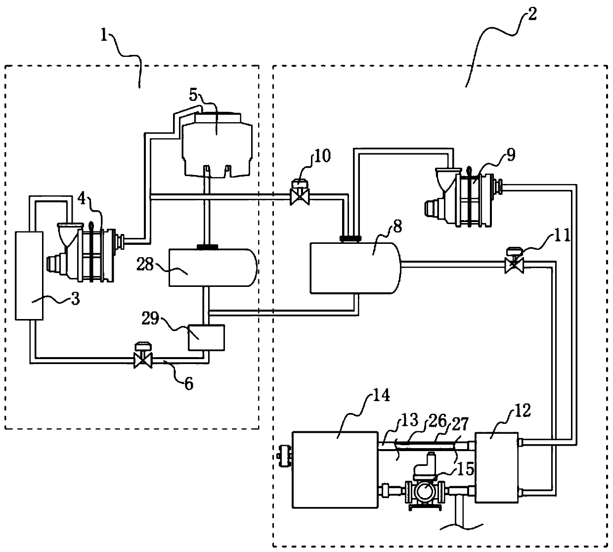
[0062] A steam refrigeration waste heat recovery system, such as figure 1 As shown, it includes a refrigeration unit 1 and a heating unit 2, and the refrigeration unit 1 includes an ammonia supply device 3, a first compressor 4, and an evaporative condenser 5 connected sequentially through pipelines; A first circulation pipe 6 is connected between them, and a pressure reducing valve 7 is arranged on the first circulation pipe 6; a liquid reservoir 28 is arranged between the evaporative condenser 5 and the first circulation pipe, and the input end of the liquid reservoir 28 is connected to the The evaporative condenser 5 is connected, and the output end of the liquid reservoir 28 is connected with the first circulation pipe; the first circulation pipe 6 is connected with an oil-water separator 29, and the oil-water separator 29 is located between the liquid reservoir 28 and the ...


PUM


Abstract

The invention discloses a steam refrigeration waste heat recovery system and method. The system comprises a refrigeration unit and a heating unit, wherein the refrigeration unit comprises an ammonia supply device, a first compressor, an evaporation type condenser and a first circulating pipeline which is provided with a reducing valve; the ammonia supply device, the first compressor, the evaporation type condenser and the first circulating pipeline are connected end to end in sequence; the heating unit comprises a first flow valve, a second flow valve, a water tank, a cooler, the lower discharging end of which is communicated with the first circulating pipeline, a second compressor, the air inlet end of which is communicated with the air outlet end of the cooler, a heat recoverer, the airinlet end of which is communicated with the air outlet end of the second compressor, and a second circulating pipeline which is provided with a circulating pump; the air outlet end of the first compressor, the first flow valve and the air inlet end of the cooler are communicated in sequence; the heat recoverer and the water tank are communicated end to end through the second circulating pipeline;and the lower discharging end of the heat recoverer, the second flow valve and the cooler are communicated in sequence. According to the system and method, the waste heat of the refrigeration unit andthe heating unit are sufficiently utilized, so that the condensation pressure of the refrigeration unit is reduced, the refrigeration efficiency and heat recovery utilization rate are improved, the energy is saved and the environment is protected.

Description

technical field [0001] The invention relates to the technical field of steam production, more specifically, it relates to a steam refrigeration waste heat recovery system and method. Background technique [0002] With the increasing depletion of human energy, how to reduce energy consumption, promote green energy, and realize energy recovery and recycling is becoming a topic of concern to countries all over the world. The existing refrigerating unit includes a compressor, a condenser, an expansion valve and an evaporator connected in sequence through pipelines; the refrigerating fluid enters the compressor in a vapor-saturated state, and the refrigerating fluid is compressed into a superheated vapor state at a higher pressure; then, The refrigerant fluid in the superheated vapor state is cooled by the condenser and condensed into a saturated liquid; after that, the saturated liquid flows through the expansion valve to reduce the pressure; finally, the liquid and vapor refrig...

Claims


Application Information

Patent Timeline
Patent Type & Authority Applications(China)
IPC IPC(8): F25B29/00F25B41/04F25B41/20
CPCF25B29/003F25B41/20
Inventor 冷松刘富刘晓芳沈奇陈志坚张永青张发天林开隆
Owner 福建正大食品有限公司
Why Eureka
Try Eureka