Wide color gamut backlight source for display of LED combined with perovskite quantum dot glass-ceramics

A technology of glass-ceramics and quantum dots, which is applied in the field of backlight, can solve the problems of performance aging, narrow luminous spectrum, and low lifespan, and achieve the effect of performance improvement and high luminous quantum efficiency

Active Publication Date: 2019-12-03
DALIAN MARITIME UNIVERSITY
View PDF6 Cites 7 Cited by
  • Summary
  • Abstract
  • Description
  • Claims
  • Application Information

AI Technical Summary

Problems solved by technology

Similarly, the combination of phosphor powder and silica gel is prone to performance aging problems, and may also cause color deviation due to the different degrees of performance degradation of red phosphor powder and green phosphor powder.
[0005] 3. Blue LED chips combined with II-VI groups such as CdSe/ZnS or III-V group core-shell structure quantum dot crystal powders and thin films such as InP/ZnS: This technical solution has been mass-produced in a small amount, and the advantage is that it can improve the color gamut. It reaches the NTSC standard of 105%, but the light efficiency is poor, and the core-shell structure needs to be made, and the environmental stability and mechanical stability are very poor. It needs special anti-humidity and anti-oxidation treatment, which is prone to quantum dot displacement and has a short

Method used


Image

  • Wide color gamut backlight source for display of LED combined with perovskite quantum dot glass-ceramics
  • Wide color gamut backlight source for display of LED combined with perovskite quantum dot glass-ceramics
  • Wide color gamut backlight source for display of LED combined with perovskite quantum dot glass-ceramics

Examples


Example Embodiment

[0045] Example 1

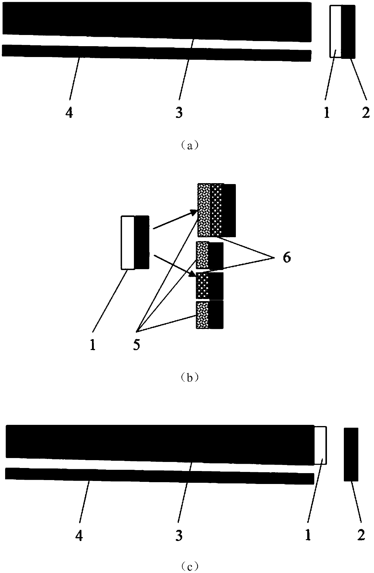
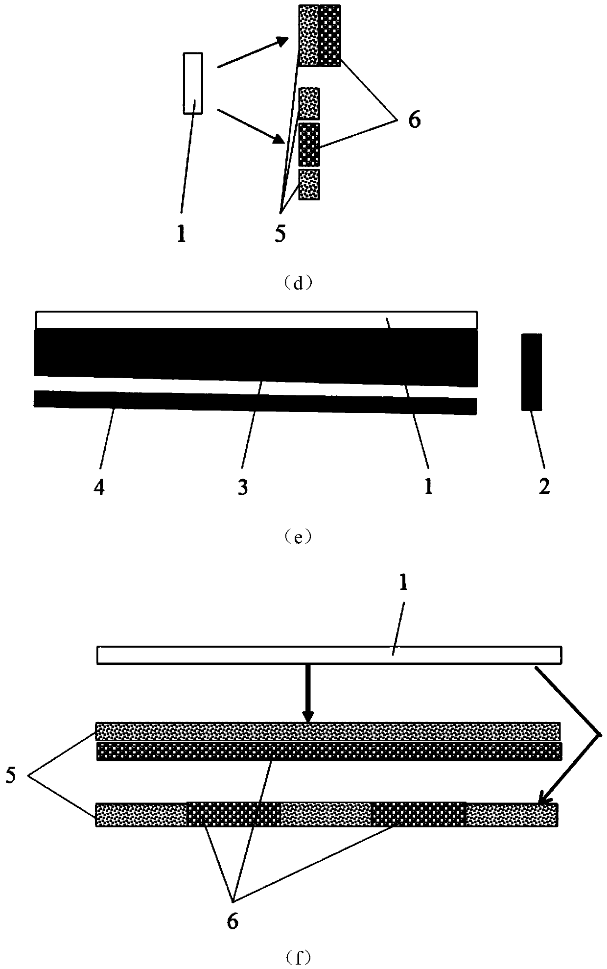
[0046] figure 2It is a schematic diagram of three applications of the LED quantum dot glass-ceramic edge-lit backlight source in the present invention, wherein (a) is the perovskite quantum dot glass-ceramic encapsulated on the LED chip, (b) is the LED of (a) and The magnified view of the quantum dot glass part, (c) is the perovskite quantum dot glass-ceramic encapsulated on the side of the light guide plate, (d) is the magnified view of the quantum dot glass part of (c), (e) is the perovskite quantum dot micro-glass The crystal glass is encapsulated on the back surface of the light guide plate, and (f) is an enlarged view of the quantum dot glass part of (e). The edge-type backlight source includes perovskite quantum dot glass-ceramic 1, blue LED2, light guide plate 3 and reflector 4, which is required to generate three-color mixed light of red, green and blue, and then pass the liquid crystal light on each pixel. The valve and color filter together cont...

Example Embodiment

[0048] Example 2

[0049] image 3 It is a schematic diagram of the application of the LED quantum dot glass-ceramic direct type backlight in the present invention. like image 3 As shown, the direct type backlight source includes blue LED2, reflector 4, green perovskite quantum dot glass-ceramic 5, red perovskite quantum dot glass-ceramic 6, diffusion film 7, brightness enhancement film 8, double enhancement film The bright film 9 and the LCD panel 10 containing the color filter are required to generate three-color mixed light of red, green and blue, and then control the output of red light, The ratio of green to blue light.

[0050] like image 3 As shown, the direct type backlight is suitable for perovskite quantum dot glass-ceramic 1 to be packaged on the LED chip. In order to prevent the performance from being degraded due to temperature rise, a reasonable thermal design is required. 5 and the red light perovskite quantum dot glass-ceramic 6 can have a certain distan...

Example Embodiment

[0051] Example 3

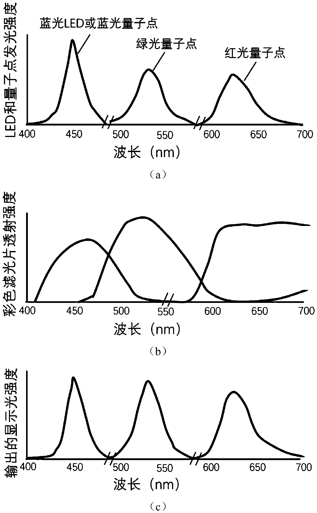
[0052] Figure 4 It is a schematic diagram of the field sequential LED backlight application of the perovskite quantum dot glass-ceramic in the present invention, wherein (a) is a blue light LED combined with a red light perovskite quantum dot glass-ceramic, a green light perovskite quantum dot glass-ceramic Schematic diagram of the red, green and blue light generated by the glass and the blue LED itself, respectively. (b) The LED combines red perovskite quantum dot glass-ceramic, green perovskite quantum dot glass-ceramic and blue light. Schematic diagram of field-sequential display of red, green, and blue light generated by perovskite quantum dot glass-ceramics, respectively. (c) A schematic diagram of red, green, and blue light flashing in sequence to form a video field in field-sequential application. The field sequential LED backlight source includes blue light LED2, green light perovskite quantum dot glass-ceramic 5, red light perovskite quantum dot g...


PUM

PropertyMeasurementUnit
Fwhmaaaaaaaaaa

Abstract

The invention provides a wide color gamut backlight source for display of LED combined with perovskite quantum dot glass-ceramics, and is used for providing a light source for the displayer. The backlight source comprises the LED and the perovskite quantum dot glass-ceramics. The perovskite quantum dot glass-ceramics comprises red light, green light and blue light perovskite quantum dot glass-ceramics. The perovskite quantum dot glass-ceramics material is CsPbX3 (X=Cl, Br, I) or CsPb (ClxBr1-x) 3 or CsPb (BrxI1-x) 3. The backlight source spectrum contains its own blue light component of the blue LED, the narrow linewidth green light component produced by exciting CsPbBr3 or CsPb (BrxI1-x) 3 quantum dot glass-ceramics by the blue LED and the narrow linewidth red light component produced byexciting CsPbI3 or CsPb (BrxI1-x) 3 quantum dot glass-ceramics by the blue LED. The backlight source spectrum can also contain the narrow linewidth blue light component produced by exciting the blue light CsPb (ClxBr1-x)3 quantum dot glass-ceramics by the short wavelength LED of which the wavelength is less than the absorption cutoff wavelength of the quantum dot, the narrow linewidth green lightcomponent produced by exciting the CsPbBr3 or CsPb (ClxBr1-x)3 quantum dot glass-ceramics by the short wavelength or blue LED and the narrow linewidth red light component produced by exciting the CsPbI3 or CsPb (ClxBr1-x)3 quantum dot glass-ceramics by the short wavelength or blue LED.

Description

technical field [0001] The invention relates to the technical field of backlight sources, in particular to a wide color gamut backlight source for display in which LEDs are combined with perovskite quantum dot glass-ceramics. Background technique [0002] At present, the main technologies and their advantages and disadvantages of wide color gamut backlight for display are as follows: [0003] 1. Blue LED chips combined with Ce 3+ : YAG yellow phosphor technology. This is an existing mass-produced technology with a high degree of technical maturity, but its disadvantages are insufficient red and green light components, and a low color gamut, which only meets 72% of the color gamut standard of the National Television Standards Committee (NTSC), and cannot meet wide-bandwidth requirements. Application of color gamut display. The combination of phosphor powder and silica gel is also prone to performance aging problems. [0004] 2. Blue light, purple light or near ultraviolet...

Claims


Application Information

Patent Timeline
IPC IPC(8): H01L33/50H01L25/075H01L33/48
CPCH01L25/0753H01L33/483H01L33/502
Inventor 张希珍陈宝玖于涛
Owner DALIAN MARITIME UNIVERSITY
Why Eureka
Try Eureka