
High-resolution high-speed laser three-dimensional imaging system

A laser three-dimensional imaging, high-resolution technology, applied in the field of aerospace optical remote sensing, can solve the problems of low ranging accuracy of single-photon area array detectors, weak anti-interference ability of background light, large field of view angle of receiving lens, etc., to achieve good Anti-background light interference ability, background light reduction, and long-range effects

Inactive Publication Date: 2019-12-10
BEIJING INST OF CONTROL ENG
View PDF7 Cites 5 Cited by
  • Summary
  • Abstract
  • Description
  • Claims
  • Application Information

AI Technical Summary

Problems solved by technology

If this kind of system adopts non-coaxial transmission and reception, the viewing angle of the receiving lens is large, the received background light noise is large, and the ability to resist background light interference is weak
[0006] Although the 3D image resolution and image frame rate of the laser 3D imaging system of the area array detector receiving type are very high, both single-photon area array detectors and area array detectors working in the linear region have obvious shortcomings.
Single-photon area array detectors have very low ranging accuracy and dark count noise; the back-end signal processing circuits of area array detectors working in the linear region are complicated, and the power consumption is extremely high, so they have no practical value

Method used


Image

  • High-resolution high-speed laser three-dimensional imaging system
  • High-resolution high-speed laser three-dimensional imaging system
  • High-resolution high-speed laser three-dimensional imaging system

Examples


Embodiment Construction

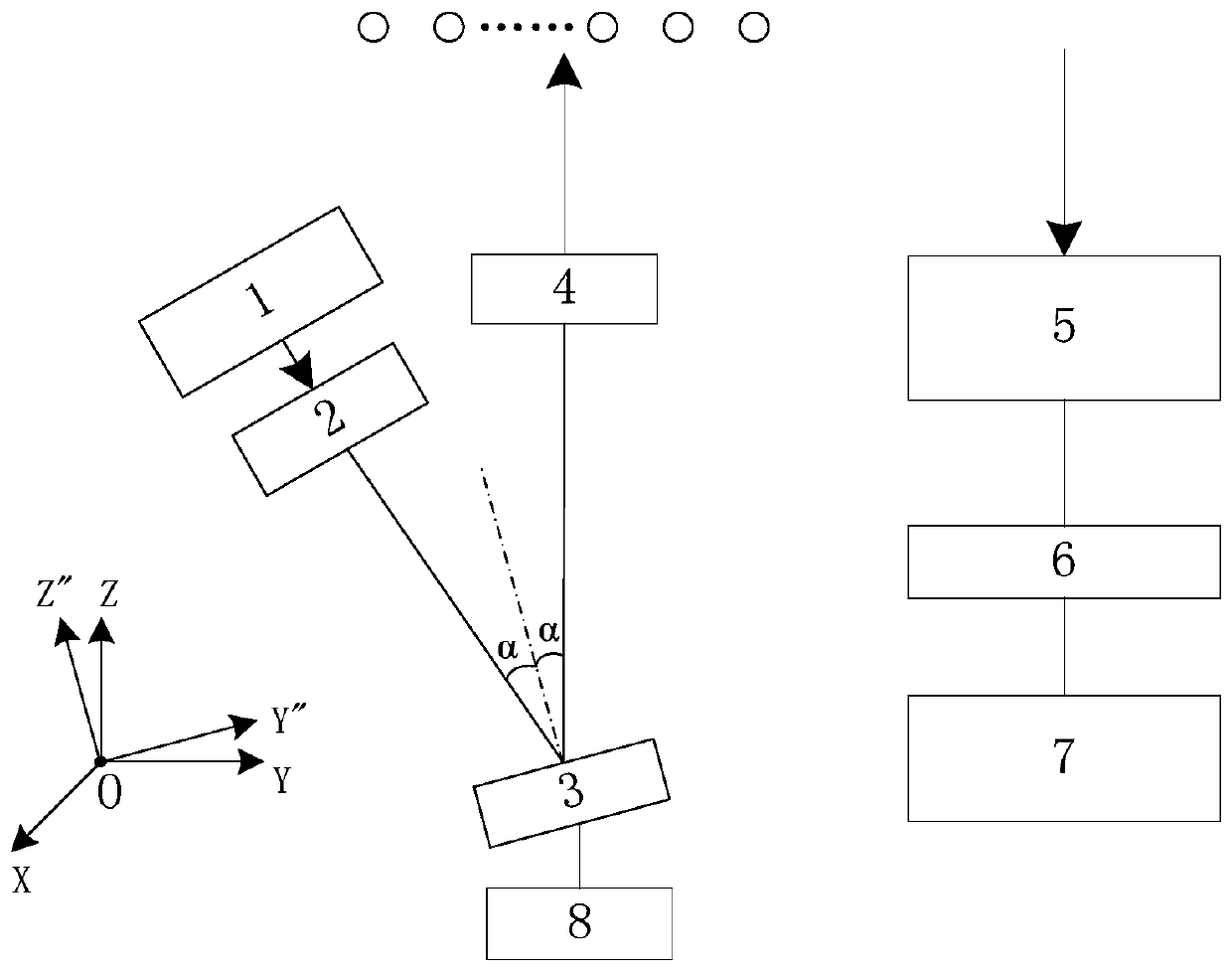
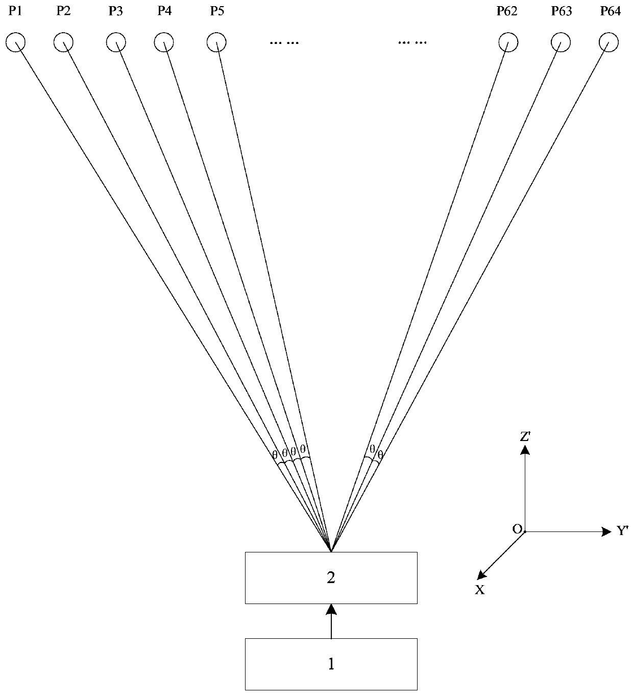
[0036] The basic idea of ​​the present invention is to propose a high-resolution and high-speed laser three-dimensional imaging system, including a laser, a grating, a scanning device, an angle magnifying lens, a receiving lens, a detector, a signal processor and a scanning device driver, wherein the laser and the grating are composed of The light source emits a line-array point array laser, the scanning device, the scanning device driver, and the angle magnifying lens form an optical scanning system, so that the line-array point array laser sweeps the target area with a preset trajectory, and the receiving lens, detector, and signal processor form an optical scanning system. The receiving system receives the echo light reflected by the target end to form a three-dimensional point cloud image of the target area. The invention has the advantages of high dynamics, high resolution, low cost, low power consumption, miniaturization, etc., and can overcome the incompatibility between...


PUM


Abstract

The invention discloses a high-resolution high-speed laser three-dimensional imaging system. The system comprises a laser (1), a grating (2), a scanning device (3), an angle amplifying lens (4), a receiving lens (5), a detector (6), a signal processor (7) and a scanning device driver (8), wherein the laser and the grating form a light source; the scanning device, the scanning device driver and theangle amplifying lens form an optical scanning system, so that the linear array point array laser scans a target area in a preset track; the receiving lens, the detector and the signal processor forman optical receiving system to receive echo light reflected by a target end to form a three-dimensional point cloud image of the target area. The system has the advantages of high dynamic, high resolution, low cost, low power consumption, miniaturization and the like, and overcomes the contradiction that the scanning speed of the traditional three-dimensional imaging system and the aperture of the receiving optical system as well as the image resolution and the image frame rate cannot be harmonized.

Description

technical field [0001] The invention belongs to the field of aerospace optical remote sensing, and relates to a high-resolution and high-speed laser three-dimensional imaging system, which can be used to measure the three-dimensional shape of a target object. Background technique [0002] Laser 3D imaging is playing an increasingly important role in the space, military, and civilian fields. In the field of space, it can be applied to high-precision three-dimensional terrain mapping for deep space exploration of extraterrestrial bodies, landing navigation and obstacle avoidance, as well as space approach and operation of non-cooperative targets, and all-round autonomous rendezvous and docking of non-cooperative targets. In the military field, it can be applied to aerial refueling of drones, blind landing of helicopters and carrier-based aircraft, etc. In the civilian field, it can be applied to autonomous navigation of unmanned vehicles, high-precision three-dimensional map ...

Claims


Application Information

Patent Timeline
Patent Type & Authority Applications(China)
IPC IPC(8): G01B11/24G01S17/06G01S7/481
CPCG01B11/24G01S17/06G01S7/481
Inventor 朱飞虎郭绍刚郑岩张运方王立王晓磊田玉松
Owner BEIJING INST OF CONTROL ENG
Learn More