Efficient air-cooling gas-phase liquid nitrogen biological storage apparatus, use method and applications thereof

A storage device and liquid nitrogen technology, which can be used in applications, preservation of human or animal bodies, animal husbandry, etc., can solve the problems of large temperature fluctuations inside the tank and large temperature differences between the top and bottom of the tank, so as to avoid liquid nitrogen overflow and balance Temperature, the effect of high-efficiency cooling temperature

Active Publication Date: 2019-12-20
天晴干细胞股份有限公司
View PDF5 Cites 3 Cited by
  • Summary
  • Abstract
  • Description
  • Claims
  • Application Information

AI Technical Summary

Problems solved by technology

[0005] The present invention proposes a high-efficiency air-cooled gas-phase liquid nitrogen biological storage device and its use method and application in order to solve the problems o

Method used


Image

  • Efficient air-cooling gas-phase liquid nitrogen biological storage apparatus, use method and applications thereof
  • Efficient air-cooling gas-phase liquid nitrogen biological storage apparatus, use method and applications thereof
  • Efficient air-cooling gas-phase liquid nitrogen biological storage apparatus, use method and applications thereof

Examples


specific Embodiment approach 1

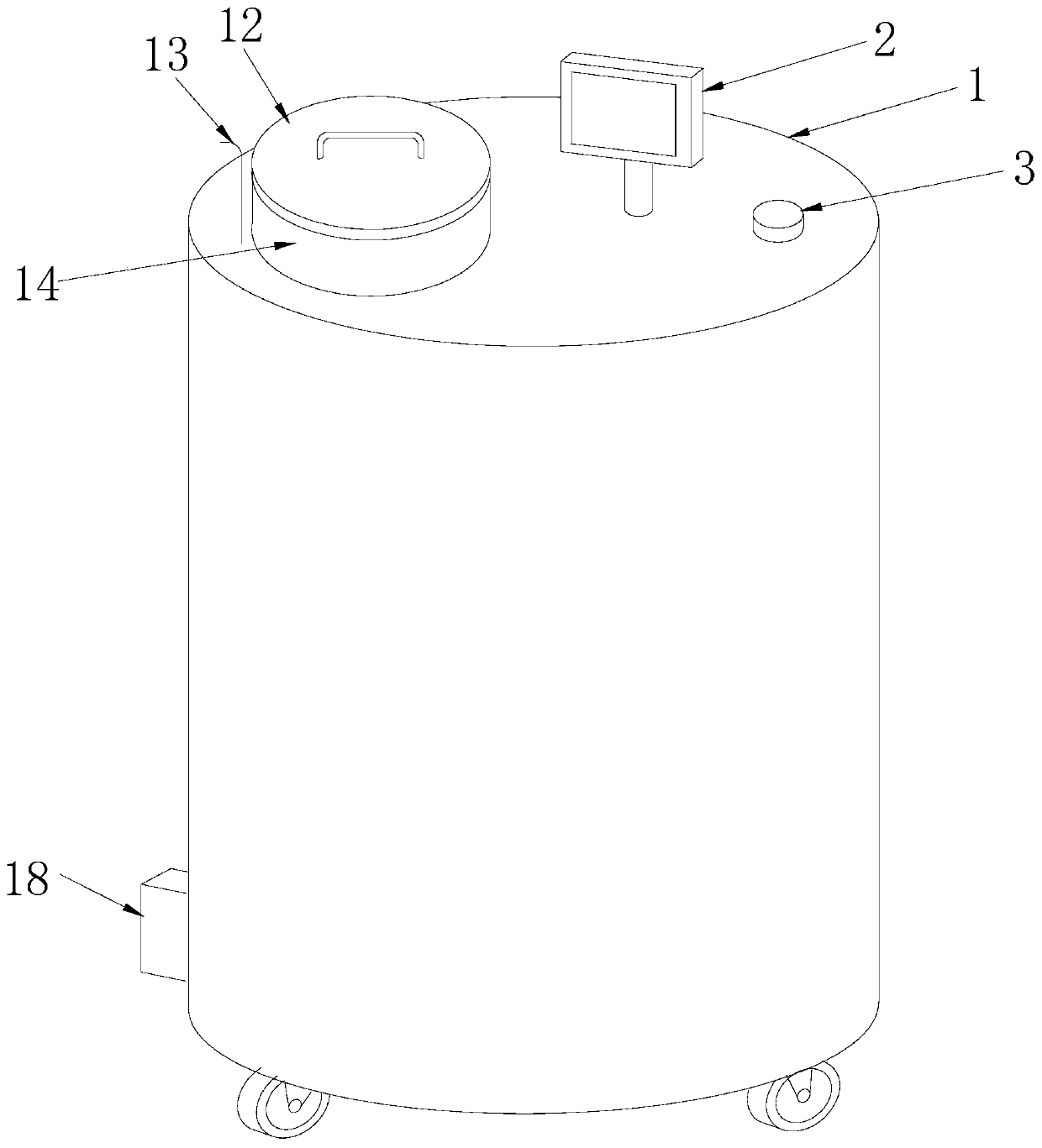
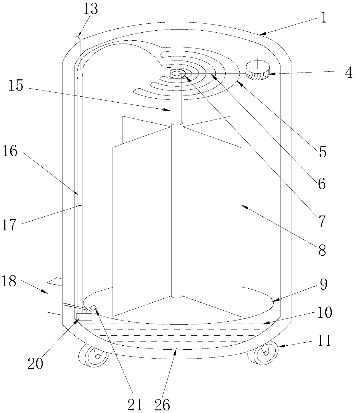
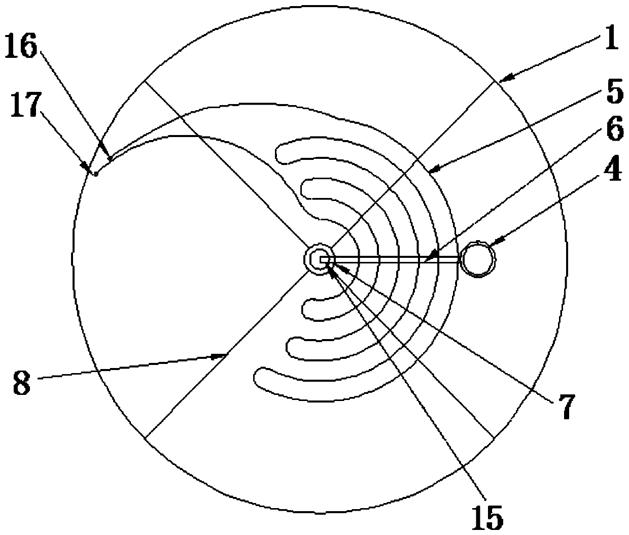
[0030] Embodiment 1: The high-efficiency air-cooled gas-phase liquid nitrogen biological storage device in this embodiment consists of a tank body 1, a control display 2, a centrifugal fan 4, a liquid nitrogen coil 5, a sample turntable 9, a central axis 15, a grid 8 and a cryogenic pump 20; the centrifugal fan 4, the liquid nitrogen coil 5, the sample turntable 9, the central axis 15, the grid 8 and the cryogenic pump 20 are arranged inside the tank body 1, the top of the tank body 1 is provided with an upper cover plate, and the control display 2 is fixed On the upper cover plate; the upper cover plate of the tank body 1 is provided with an access opening 14, and the access opening 14 is provided with an access opening cover plate 12;

[0031] The lower part of the tank body 1 is filled with liquid nitrogen 10, the inner bottom of the tank body 1 is provided with a vertical support column 27, the central axis 15 is a hollow cylinder, and the lower end of the central axis 15 i...

specific Embodiment approach 2

[0041] Embodiment 2: The difference between this embodiment and Embodiment 1 is that the upper cover plate of the tank body 1 is provided with a vacuum layer, and the upper surface of the upper cover plate of the tank body 1 corresponding to the centrifugal fan 4 is provided with First motor 3, the power output shaft of the first motor 3 passes through the vacuum layer of the upper cover plate of the tank body 1 and is connected with the power input shaft of the centrifugal fan 4; the material of the power output shaft of the first motor 3 is low temperature resistant plastic. Other steps and parameters are the same as those in the first embodiment.

[0042] In this embodiment, the motor is externally installed to avoid the influence of additional heat sources on the temperature inside the tank. The power output shaft connected between the motor and the cryogenic pump is made of low-temperature resistant plastic, which avoids the conduction of cold energy inside the tank to th...

specific Embodiment approach 3

[0043] Embodiment 3: This embodiment differs from Embodiment 2 in that: a mechanical seal is provided between the power output shaft of the first motor 3 and the upper cover of the tank body 1 . Other steps and parameters are the same as in the second embodiment. Mechanical seals can prevent liquid nitrogen from overflowing.


PUM

PropertyMeasurementUnit
Diameteraaaaaaaaaa

Abstract

The invention discloses an efficient air-cooling gas-phase liquid nitrogen biological storage apparatus, a use method and applications thereof, and relates to a biological storage apparatus, a use method and applications thereof. A purpose of the present invention is to solve the problems of large temperature difference between the upper portion and the lower portion in the tank body of the existing gas-phase liquid nitrogen biological storage tank, and large temperature fluctuation in the tank body. The apparatus comprises a tank body, a control display device, a centrifugal fan, a liquid nitrogen coil pipe, a sample rotating disc, a central shaft, a grid and an ultralow-temperature pump, wherein a round disc wind port is arranged at the center of the lower surface of the upper cover plate of the tank body, a gas channel is arranged between the round disc wind port and the centrifugal fan, and the liquid nitrogen coil pipe is fixed between the centrifugal fan and the round disc wind port. According to the present invention, the apparatus can perform quick-cooling operation and storage operation, and can be used for storage of large lactation organisms, cryopreservation racks, biological cells or viruses; with the apparatus and the method, the problems of large temperature difference and large temperature fluctuation in the tank body are solved, and the liquid nitrogen consumption is reduced; and the apparatus and the method are suitable for gas-phase liquid nitrogen biological storage devices and applications.

Description

technical field [0001] The invention relates to a biological storage device and its use method and application. Background technique [0002] Liquid nitrogen tanks are widely used in hospitals and laboratories, and are mainly divided into liquid phase storage and gas phase storage. Liquid nitrogen tanks are used for cryopreservation of biological materials such as cells and tissues. At present, in the field of biological research and clinical treatment, gas-phase liquid nitrogen biological storage tanks can ensure long-term stable storage of cells, and can avoid multi-sample biological contamination caused by liquid phase, especially in cord blood banks, various stem cell banks, and biological tissue samples. widely used in the library. [0003] The gas-phase liquid nitrogen biological storage tank keeps biological samples in a low-temperature liquid nitrogen vapor environment through the continuous evaporation of liquid nitrogen in the tank, thereby realizing ultra-low te...

Claims


Application Information

Patent Timeline
IPC IPC(8): A01N1/00A01N1/02
CPCA01N1/00A01N1/0252
Inventor 张宇张怡刘艳青
Owner 天晴干细胞股份有限公司
Why Eureka
Try Eureka