
scr urea mixer for aftertreatment system of diesel internal combustion engine

A diesel internal combustion engine and mixer technology, applied in the field of environmental treatment, can solve problems such as uneven mixing of hot exhaust gas and clogging of SCR catalyst, and achieve the effect of solving urea deposition and crystallization

Active Publication Date: 2020-06-30
SINOCAT ENVIRONMENTAL TECH
View PDF8 Cites 1 Cited by
  • Summary
  • Abstract
  • Description
  • Claims
  • Application Information

AI Technical Summary

Problems solved by technology

The SCR mixer in the technical scheme of the existing diesel internal combustion engine post-treatment system in China widely adopts the inner layer and outer layer perforated pipe structure. The first atomization, and then under the action of the outer perforation of the outer pipe, the second atomization is carried out, and then enters the air intake chamber; during the working process of the mixer, there is uneven mixing of the urea aqueous solution and the hot exhaust gas discharged from the diesel internal combustion engine. There are a large number of urea crystals inside and on the end surface of the SCR catalyst, causing problems such as blockage of the SCR catalyst

Method used


Image

  • scr urea mixer for aftertreatment system of diesel internal combustion engine
  • scr urea mixer for aftertreatment system of diesel internal combustion engine
  • scr urea mixer for aftertreatment system of diesel internal combustion engine

Examples


Embodiment Construction

[0027] The present invention will be further described below in conjunction with the specific embodiments, which further illustrate the principles of the present invention and do not limit the present invention in any way, and the same or similar technologies as the present invention do not exceed the protection scope of the present invention.

[0028] In conjunction with the attached drawings.

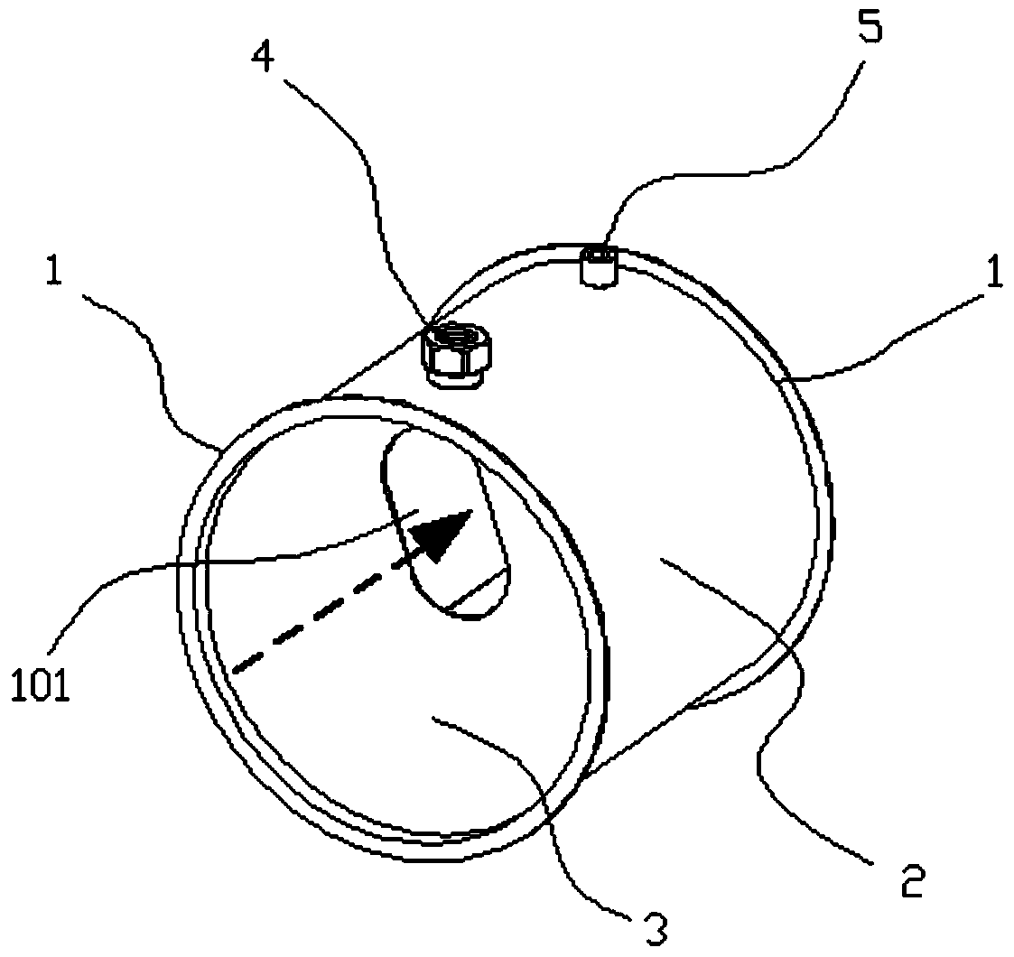
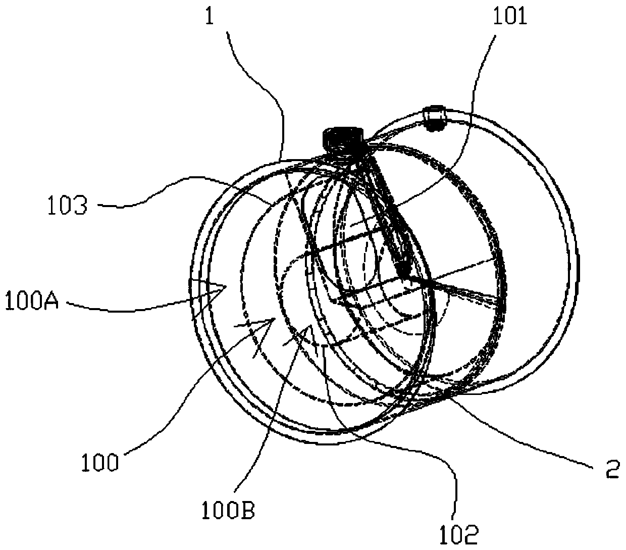
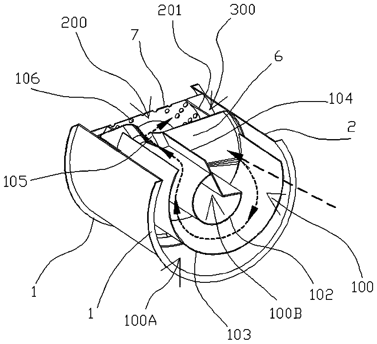
[0029] The SCR urea mixer for diesel engine exhaust after-treatment system includes a cylindrical shell 2 and a urea nozzle seat located in the shell. The intake end of the mixer has three independent and isolated chambers from the inner wall of the shell to the center. They are the heat-sealed isolation chamber 100A at the intake end, the vortex mixing chamber 100, and the central sealing chamber at the intake end 100B; the exhaust end of the mixer has two independent and isolated chambers, which are the exhaust mixing chamber 200 and Exhaust thermal isolation chamber 300 .

[0030]...


PUM


Abstract

The invention discloses an SCR urea mixer for an aftertreatment system of a diesel internal combustion engine. It includes a cylindrical shell and a urea nozzle. The front end of the shell is provided with a vortex mixing chamber, and the rear end is provided with an exhaust mixing chamber; the urea nozzle is arranged on the wall of the vortex mixing chamber; The gas flow mixing chamber of the spiral structure with convergent flow characteristics, the front face, along the axial direction of the shell, and the outer peripheral edge of the spiral structure are provided with air inlets, the connection between the vortex mixing chamber and the exhaust mixing chamber, along the edge of the core of the spiral structure An exhaust port is arranged in the circumferential direction, a round hole is arranged in the center of the rear end surface of the exhaust mixing chamber, and a plurality of equalizer plate exhaust holes are evenly arranged on the radially outer periphery of the round hole. The mixer of the present invention makes full use of the exhaust hot tail gas flow to transmit, crush and atomize the urea droplets, and fully and evenly mixes with the hot tail gas, which solves the problem of urea deposition and crystallization, and the mixer has uniform air flow and ammonia gas It satisfies the requirements of emission regulations very well.

Description

technical field [0001] The invention belongs to the technical field of environmental treatment, in particular to the technical field of design and manufacture of exhaust gas purification equipment, relates to a diesel internal combustion engine exhaust aftertreatment technology, and in particular relates to a diesel internal combustion engine aftertreatment system SCR urea mixer. Background technique [0002] At present, the exhaust emission reduction technology used in the exhaust after-treatment system of diesel internal combustion engines has the following two technical approaches and routes: First, by optimizing the combustion system in the diesel engine cylinder, the purification of in-cylinder particulates in the engine and the catalytic reduction of the engine after-treatment system are realized. Nitrogen oxides, namely SCR selective catalytic reduction technology; the second is the use of diesel engine in-cylinder nitrogen oxide purification EGR (engine exhaust gas re...

Claims


Application Information

Patent Timeline
Patent Type & Authority Patents(China)
IPC IPC(8): F01N3/28F01N3/20
CPCF01N3/2066F01N3/2892F01N2610/02F01N2610/1453Y02T10/12
Inventor 张流俊郝俊修陈启章李建唐国海张怡宋翔肖宇刚任德全
Owner SINOCAT ENVIRONMENTAL TECH
Learn More