Carbon dioxide separation membrane and production method therefor

A carbon dioxide and separation membrane technology, applied in the direction of separation methods, chemical instruments and methods, gardening methods, etc., can solve the problems of no ionic liquid, etc., achieve the effects of suppressing stickiness, excellent operability, and realizing miniaturization

Active Publication Date: 2020-01-07
DAICEL CHEM IND LTD
View PDF11 Cites 1 Cited by
  • Summary
  • Abstract
  • Description
  • Claims
  • Application Information

AI Technical Summary

Problems solved by technology

However, there is no mention of ionic liquids in this literature
[0011] In addition, in Patent Documents 2 to 4, there are mainly descriptions for industrial use, for example, the use of separating and recovering (or removing) carbon dioxide from waste gas discharged from factories, etc., and energy resources (such as natural gas, etc.), but there is no reference to the application of carbon dioxide to plants. Any description of the supply of carbon dioxide concentrated from the atmosphere for agricultural purposes (fertilization purposes)

Method used


Image

  • Carbon dioxide separation membrane and production method therefor
  • Carbon dioxide separation membrane and production method therefor
  • Carbon dioxide separation membrane and production method therefor

Examples


preparation example Construction

[0087] The method for producing such a porous film of thermoplastic resin is not particularly limited, and conventional methods, such as a method using phase separation of a resin solution, a method of stretching a resin film, or irradiating a resin film with high-energy rays such as α-rays, can be used. method etc. to prepare.

[0088] In addition, in order to adjust the wettability (or contact angle) of the liquid (A) containing the ionic liquid, the IL-incompatible porous layer (B) can be subjected to a conventional surface treatment (for example, JP-A-6-9810 The treatment described in , that is, the treatment of attaching a cross-linked body derived from an ethylenically unsaturated monomer having a fluoroalkyl group, etc.).

[0089] Commercially available products can be used as the IL-incompatible porous layer (B), and examples thereof include "C-pore" manufactured by Ube Maxell Co., Ltd., "U-Pore" manufactured by Ube Industries Co., Ltd., and "U-Pore" manufactured by Me...

Embodiment 1

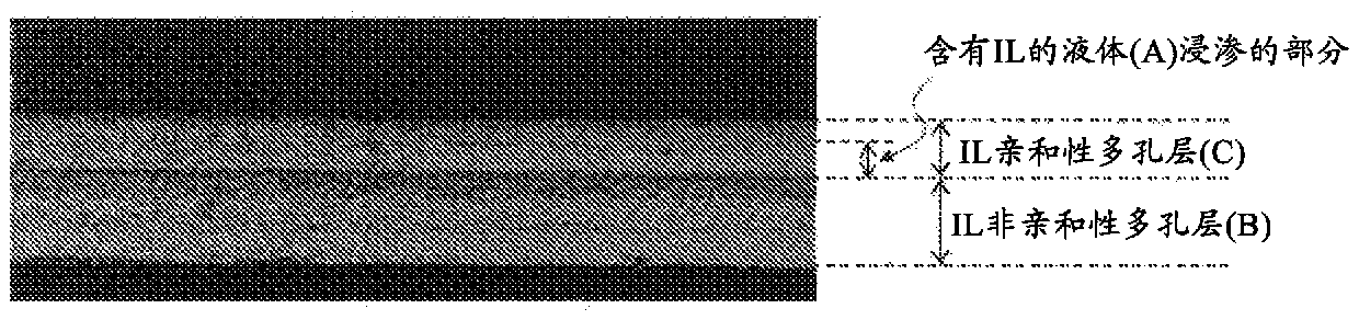
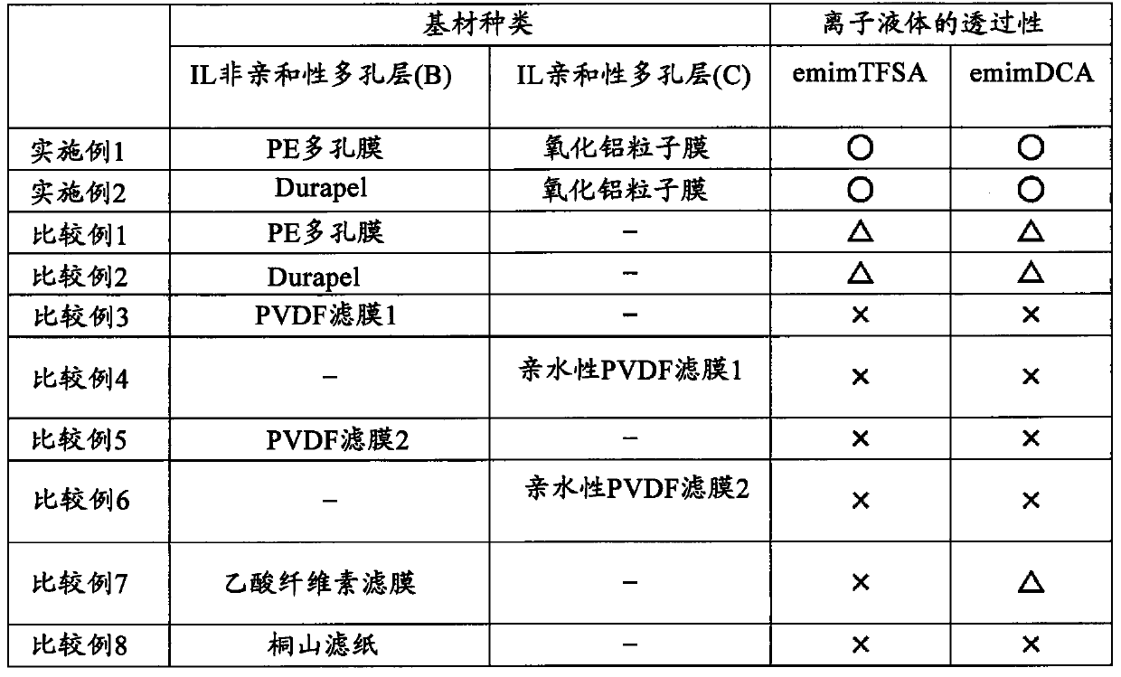
[0161] The above-mentioned alumina particles were mixed with water to prepare an alumina particle dispersion (alumina particle slurry) having a concentration of 8 to 10% by weight. On the PE porous membrane as the IL non-affinity porous layer (B), the obtained alumina particle slurry was coated by wire bar coating, and dried at 100°C for 1 minute to form an IL affinity layer (B). And the porous layer (C). The alumina particle slurry was applied so that the dried IL-affinity porous layer (C) had a thickness of 5 μm. The permeability of the ionic liquid was evaluated using the IL-free laminate. It should be noted that the ionic liquid was dripped on the IL-affinity porous layer (C) side of the fixed IL-free laminate, and on the opposite side of the dripped surface (IL-non-affinity porous layer (B) side) was decompressed.

Embodiment 2

[0163] In addition to adding 1% by weight of isopropyl alcohol (IPA) to the aluminum oxide particle dispersion liquid, and using Durapel as the IL non-affinity porous layer (B), the same as the example 1 A laminate not containing IL was prepared in the same manner, and the permeability of the ionic liquid to the obtained laminate not containing IL was evaluated.


PUM

PropertyMeasurementUnit
particle sizeaaaaaaaaaa
thicknessaaaaaaaaaa
thicknessaaaaaaaaaa

Abstract

The carbon dioxide separation membrane includes a porous layer having affinity with ionic liquids (C), the layer holding an ionic liquid-containing liquid (A) within voids therein, and a porous layerlacking affinity with ionic liquids (B). The porous layer having affinity with ionic liquids (C) may include an inorganic material (e.g., metal oxide particles having an average particle size of approximately 0.001 to 5[mu]m on a number basis). The average thickness of the porous layer having affinity with ionic liquids (C) may be approximately 0.01 to 10[mu]m. The porous layer having affinity with ionic liquids (C) may include 0.1 to 99 volume parts of the ionic liquid-containing liquid (A) with respect to 100 volume parts of voids therein. The carbon dioxide separation membrane may be used for fertilizing plants with carbon dioxide. The carbon dioxide separation membrane allows the size of a carbon dioxide concentrating device to be reduced and allows the device to be smoothly operated.

Description

technical field [0001] The present invention relates to a carbon dioxide separation membrane suitable for fertilization of carbon dioxide in the agricultural field, a method for producing the same, and a carbon dioxide concentrator equipped with the above carbon dioxide separation membrane. Background technique [0002] In agricultural or horticultural facilities (such as greenhouses, plastic greenhouses, plant factories, etc.), during the daytime and when there is a lot of sunlight, the photosynthesis of plants becomes active, so it is easy to cause carbon dioxide (carbon dioxide gas) in the facilities. or CO 2 ) concentration decreases. If the low carbon dioxide concentration in the facility continues, the photosynthesis of the plants will not be sufficient, and the growth may be hindered and the growth rate may be reduced. Therefore, fertilization with carbon dioxide is performed for the purpose of promoting the growth of plants and increasing the yield. [0003] As a ...

Claims


Application Information

Patent Timeline
Patent Type & Authority Applications(China)
IPC IPC(8): B01D69/00A01G7/02A01G9/18B01D53/22B01D61/38B01D69/10B01D69/12
CPCA01G7/02B01D61/38B01D69/12B01D67/0046B01D67/0079B01D71/025B01D71/26B01D69/02B01D2325/12B01D53/228B01D2257/504Y02C20/40
Inventor 中村敏和岩谷真男铃木崇将后藤友寻
Owner DAICEL CHEM IND LTD
Why Eureka
Try Eureka