A Rapid Surface Renewal Tower Biological Filter

A biological filter and tower technology, applied in the field of industrial wastewater treatment devices, can solve the problems of packing blockage, shorten the operation period of the equipment, and the thickness of the packing layer is large, and achieve the effects of accelerating peeling, avoiding wall flow effect, and shortening the time.

Active Publication Date: 2021-04-06
TAIZHOU QINGRUN ENVIRONMENTAL PROTECTION TECH CO LTD
View PDF5 Cites 0 Cited by
  • Summary
  • Abstract
  • Description
  • Claims
  • Application Information

AI Technical Summary

Problems solved by technology

However, if such a redistributor is used in a tower biofilter, as mentioned earlier, due to the entrainment of the biofilm in the liquid phase, due to the liquid phase at the bottom periphery of each section of the filter material and due to the existence of the distributor The enrichment in the middle of the top of the packing section will cause partial blockage of the packing in this area, thereby greatly shortening the equipment operation cycle
In addition, due to the large thickness of the packing layer in the tower biofilter, it is difficult for the flushing water to fully scrub the surface of the packing

Method used


Image

  • A Rapid Surface Renewal Tower Biological Filter
  • A Rapid Surface Renewal Tower Biological Filter
  • A Rapid Surface Renewal Tower Biological Filter

Examples


Embodiment 1

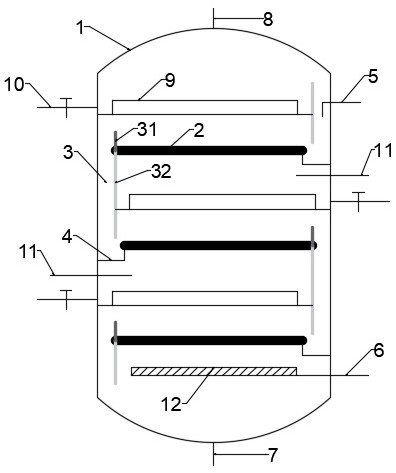
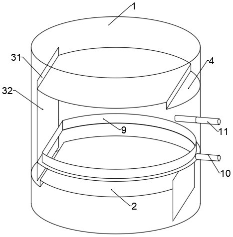
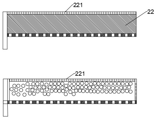
[0028] A tower-type biological filter with rapid surface renewal, including a tower body 1, a sewage inlet 5 and an exhaust port 8 arranged on the top of the tower body 1, and a water outlet 7 and an air inlet 6 at the bottom of the tower body 1 , the inner interval of the tower body 1 is provided with several layers of trays 2, the trays 2 are sieve trays, and the upstream and downstream of each tray 2 are respectively equipped with a liquid receiving tray 4 and a downcomer 3; The downcomer 3 is formed by an overflow weir 31 located on the upper surface of the tray 2, a downcomer wall 32 located on the lower surface of the tray 2 and the inner wall of the tower body 1; A packing layer 22 is arranged on it; the height of the packing layer 22 does not exceed the overflow weir 31; the packing layer 22 includes a limiting element 221, and the limiting element 221 is surrounded by the tray 2 and the overflow weir 31 The packing bin where the packing is placed; the limiting element...

Embodiment 2

[0031] The difference from Example 1 is that the tray 2 is a valve tray, and several float valves 21 are arranged on the valve tray. The valve surface of the float valve 21 includes a sieve hole 212 in the middle and The valve edge 211 on the edge of the valve surface; the float valve 21 also includes two opposite valve legs 213 and a valve foot 216 at the bottom of the valve legs 213, and the valve foot 216 is allowed to be bent during installation; The corresponding sides of the two valve legs 213 are connected by a grid plate 215, and several grid holes 214 are arranged on the grid plate 215; The widths are all smaller than the smallest dimension of the granular filler.

Embodiment 3

[0033] The difference from Embodiment 2 is that the float valve 21 is a guide float valve, and the guide float valve is provided with a guide hole 217 at the middle and lower part of the valve leg 213 on one side, and the guide hole 217 is only exposed when the gas phase is strongly impacted. The upper surface of the tray 2; two kinds of float valves 21 of type A and type B are arranged on the tray 2, and the guide hole 217 of the type A float valve 21 is located on the valve leg 213 on the downstream side thereof; The guide hole 217 of the type float valve 21 is located on the valve leg 213 on the upstream side thereof. The A-type and B-type float valves 21 are arranged in rows at intervals.


PUM


Abstract

The invention relates to a tower-type biological filter with rapid surface renewal, which adopts a plate-type tower structure, which eliminates the wall flow problem in the traditional packing tower; through the strong impact of the gas phase, the liquid flooding of the plate is promoted, and the surface of the packing is washed to promote the aging biofilm Falling off, the generation of flooding makes the liquid on the corresponding tray unable to flow into the lower tray; at the same time, an overflow tank is set up on the tower wall above the tray to guide the liquid entrained with the biofilm out of the tower, thereby preventing the biofilm from descending The enrichment of the tray and the resulting blockage of the lower tray; through the guide float valve set at intervals or partitions, the guide hole is opened during the strong impact of the gas phase, and the disturbance of the liquid layer on the plate is strengthened, thereby accelerating the peeling of the biofilm and shortening The time for the strong impact of the gas phase is reduced; by setting the gas supply pipe between adjacent trays, the selective flooding of any tray can be realized, and the normal operation of other trays can be kept at the same time, so that the tower biofiltration membrane can To achieve uninterrupted sewage treatment operations.

Description

technical field [0001] The invention relates to an industrial waste water treatment device, in particular to a tower-type biological filter with rapid surface renewal. Background technique [0002] Industrial wastewater is mainly divided into heavy metal wastewater, organic wastewater, ammonia nitrogen wastewater, and phosphorus wastewater according to the content of pollutants. The latter three, namely organic, ammonia nitrogen, and phosphorus-containing wastewater, are usually discharged in a mixed form. This waste water is the main cause of eutrophication and black and smelly water. At present, the mainstream treatment processes for such industrial wastewater include activated sludge method and biofilm method. Among them, in the biofilm treatment process, microorganisms attach to the surface of the filter material and grow, which can form a stable ecological condition, allowing bacteria with slow proliferation and long generation time and higher micro organisms, such as...

Claims


Application Information

Patent Timeline
Patent Type & Authority Patents(China)
IPC IPC(8): C02F3/02C02F3/10
CPCC02F3/02C02F3/10C02F2203/006C02F2303/14Y02W10/10
Inventor 徐书敏
Owner TAIZHOU QINGRUN ENVIRONMENTAL PROTECTION TECH CO LTD
Why Eureka
Try Eureka